Automatic take-up machine
A wire take-up machine, fully automatic technology, applied in the direction of thin material processing, conveying filamentous materials, transportation and packaging, etc., can solve the problems of low efficiency, cumbersome operation, unable to limit and fix the wire coil, etc.
- Summary
- Abstract
- Description
- Claims
- Application Information
AI Technical Summary
Problems solved by technology
Method used
Image
Examples
Embodiment 1
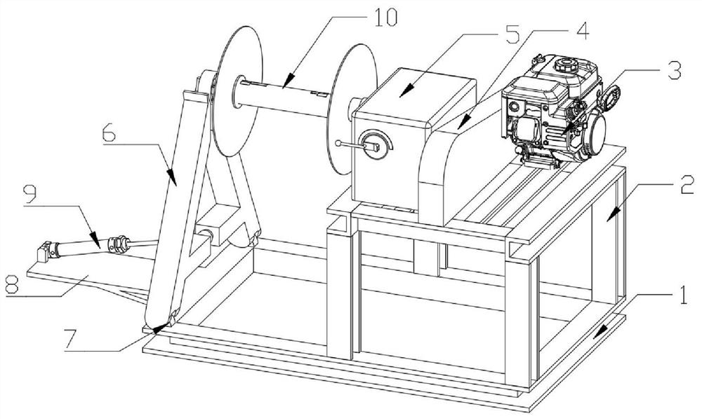
[0030] Such as Figure 1 to Figure 7 As shown, the fully automatic wire take-up machine provided by the present invention includes a base 1, a mounting frame 2 is provided on the top side wall of the base 1, a gasoline engine 3 is provided on the rear end wall of the top side of the mounting frame 2, and a mounting frame 2 The top is also provided with a transmission box 4 on the bottom wall at the left side of the gasoline engine 3, the top of the installation frame 2 is also provided with a reducer 5 on the wall at the left side of the transmission box 4, and the front and rear ends on the other side of the top of the base 1 The wall is respectively provided with a fixed seat 7, and the top of the base 1 is also provided with a support 6 above the one side of the fixed seat 7, and the front and rear end walls of the bottom of the support 6 are movably installed on the fixed seat 7 through the wall transfer groove. The side wall body is also provided with a support plate 8, a...
Embodiment 2
[0033]On the basis of Example 1, as Figure 6 and Figure 7 As shown in the adjusting mechanism of the fully automatic wire take-up machine, an installation groove 46 is provided in the outer wall of one side of the adjustment column 21, and a plurality of second fixing rods 47 are fixedly installed between the two side walls of the installation groove 46, and the second fixing rods The first compression spring 48 is set on the outer wall of 47, and a screw groove 49 is also provided in the side wall body of the adjustment column 21, and the adjustment column 21 is screwed into the first screw thread 26 installed on the outer wall of the line roller 10 side through the second connecting groove 40 , the other side wall of the fixed column 22 is fixedly installed with a limit block 50, and the wall body of the telescopic column 23 is provided with a telescopic groove 51, and the telescopic column 23 is interspersed and installed on the fixed column 22 through the telescopic groo...
Embodiment 3
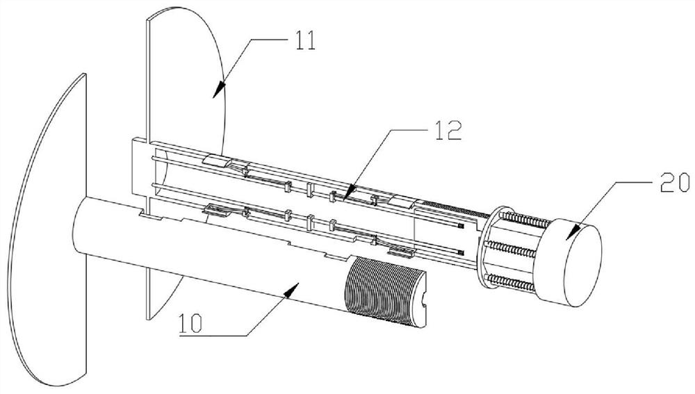
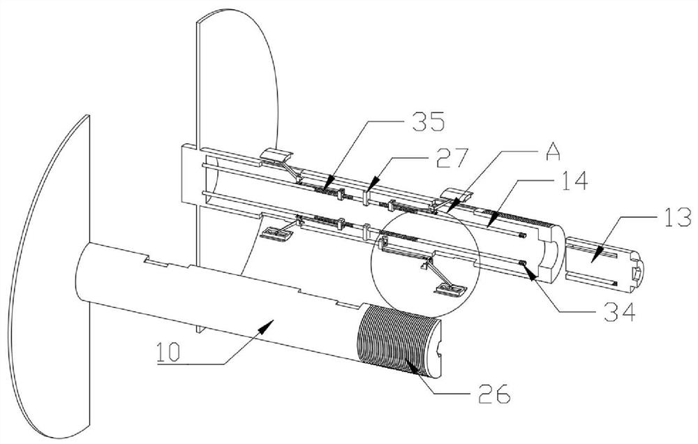
[0036] On the basis of Example 2, such as image 3 , Figure 4 and Figure 5 As shown in the limit mechanism of the fully automatic wire take-up machine, the first side baffle 11 is fixedly installed on the outer wall of one side of the wire roller 10, the first thread 26 is arranged on the outer wall of the other side of the wire roller 10, and the inner top of the wire roller 10 A second fixed block 27 is fixedly installed on the wall body in the middle of the bottom, and a storage opening 28 is respectively opened in the top and bottom side walls of the wire roller 10, and the wire roller 10 is still on the wall at the corresponding storage opening 28 sides. Limiting slots 29 are provided in the body, and the first fixed shaft 30 is fixedly installed on the side wall body of the adjustment shaft 13. The first fixed shaft 30 is inserted into the bearing in the side wall body of the line roller 10, and the first fixed shaft 30 There is also a slot 31 in the body, a chute 32...
PUM
 Abstract
Description
Claims
Application Information
 - R&D
- Intellectual Property
- Life Sciences
- Materials
- Tech Scout
- Unparalleled Data Quality
- Higher Quality Content
- 60% Fewer Hallucinations
Browse by: Latest US Patents, China's latest patents, Technical Efficacy Thesaurus, Application Domain, Technology Topic, Popular Technical Reports.
© 2025 PatSnap. All rights reserved.Legal|Privacy policy|Modern Slavery Act Transparency Statement|Sitemap|About US| Contact US: help@patsnap.com


