Radar target simulator front end and simulation method
A radar target simulation and radar target technology, applied in the field of testing radar equipment, can solve problems such as being cumbersome and unable to be used in a production test environment
- Summary
- Abstract
- Description
- Claims
- Application Information
AI Technical Summary
Problems solved by technology
Method used
Image


Examples
no. 1 approach
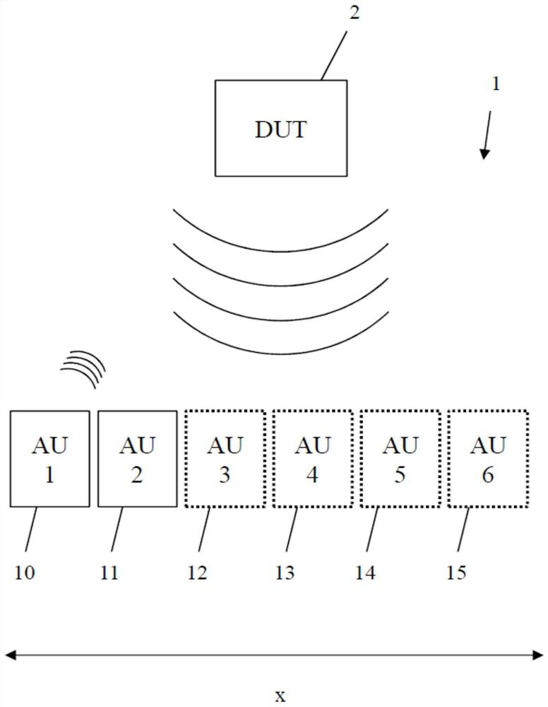
[0035] figure 1 In , a first embodiment of the radar target simulator front end 1 of the present invention and a radar device under test (DUT) 2 are shown. The radar device under test 2 is a multiple-input multiple-output (MIMO) radar device under test or a multiple-input single-output (MISO) radar device under test. Even single-input single-output (SISO) radar devices under test can be tested with this setup.
[0036] Here, the radar target simulator front end 1 comprises a plurality of antenna units (AU) 10 , 11 , 12 , 13 , 14 and 15 arranged along a first angle x to be studied relative to the radar device 2 under test. Here, antenna elements 12-15 are shown with dashed lines, indicating that these antenna elements constitute optional components. Each of the antenna elements 10-15 is configured to be selectively activated and deactivated. In the activated state, each antenna element 10-15 produces a radar reflection, while in the deactivated state, none of the antenna ele...
no. 2 approach
[0045] figure 2 , a detailed view of a second embodiment of the radar target simulator front end of the present invention is shown. Here, only a single antenna unit 10 is shown. Here, the antenna unit 10 includes a transmitting antenna (Tx) 20 and a receiving antenna (Rx) 21 . The receiving antenna 21 is configured to receive the radar signal sent by the radar device 2 under test, and the transmitting antenna 20 is configured to send the simulated scattered signal back to the radar device 2 under test.
[0046] In the simplest configuration, activation of the antenna unit 10 is achieved by connecting the transmitting antenna 20 to the receiving antenna 21 , and deactivation is achieved by disconnecting the connection between the transmitting antenna 20 and the receiving antenna 21 .
[0047] In a more complex setup, the radar target simulator front end 1 is connected to a target simulator back end (not shown here). The backend is then configured to process the radar signal...
no. 3 approach
[0057] image 3 In , another detailed diagram of an embodiment of the radar target simulator front end of the present invention is shown. Here, the inner workings of a single antenna unit 10 are shown. Here, the antenna unit 10 includes a combined transmit / receive antenna (Tx / Rx) 30 . The transmitting / receiving antenna 30 is used not only for receiving radar signals transmitted by the radar device 2 to be tested, but also for transmitting simulated scattered signals to the radar device 2 for testing.
[0058] In the simplest configuration, deactivation of the transmit / receive antenna 30 can be achieved by opening switches connecting different parts of the antenna, thereby significantly changing the frequency response of the antenna, thereby significantly reducing the magnitude of the reflected radar signal. Activation in this case takes place by switching on the connection again.
[0059] In more complex setups, such as referring to figure 2 As described, radar signals re...
PUM
 Abstract
Description
Claims
Application Information