Supercharge Your Innovation With Domain-Expert AI Agents!

Timing device having mechanism driven by mechanical driving device and power storage indicating device

A power reserve and indicating device technology, which is applied to clock drive mechanisms, mechanically driven clocks, spring ratchet mechanisms, etc., can solve problems such as increased movement space, difficult design, and complex structure.

Inactive Publication Date: 2004-02-04
ASULAB SA
View PDF0 Cites 1 Cited by
  • Summary
  • Abstract
  • Description
  • Claims
  • Application Information

AI Technical Summary

Problems solved by technology

This type of gear train usually requires several gears, thus increasing the space required for the movement and making the structure more complex
Therefore, it is relatively costly to arrange a conventional power-reserve indicating device in a movement consisting of a clockwork, and the eventual space requirements of such a device lead to design difficulties which cannot always be overcome, in particular This is especially true for small-sized movements, such as ladies' watch movements

Method used


Image

  • Timing device having mechanism driven by mechanical driving device and power storage indicating device
  • Timing device having mechanism driven by mechanical driving device and power storage indicating device
  • Timing device having mechanism driven by mechanical driving device and power storage indicating device

Examples


Embodiment Construction

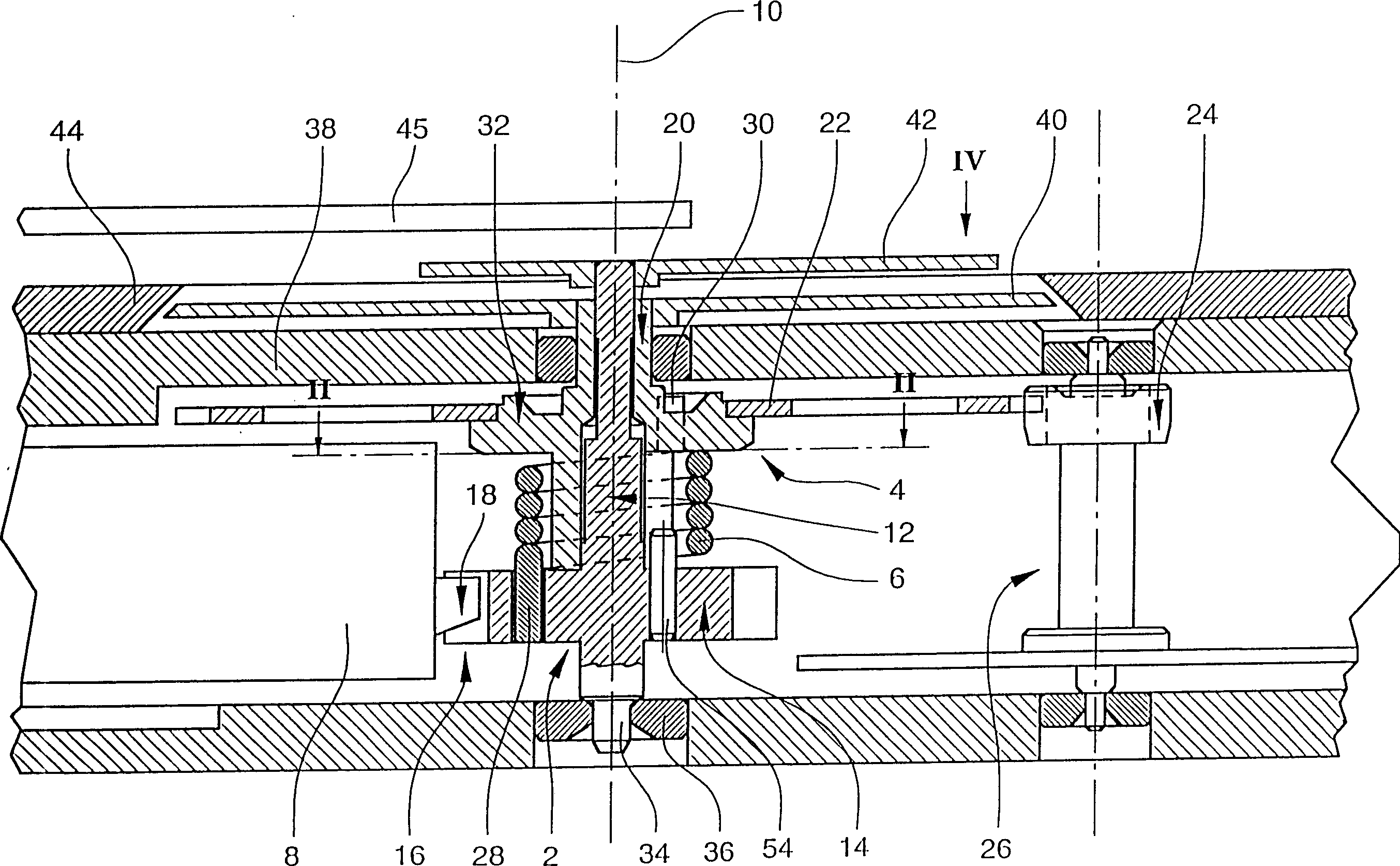
[0019] refer to Figures 1 to 4 , presenting a first embodiment of a mechanical timepiece comprising a power reserve indicating device according to the invention.

[0020] The power reserve indicating device comprises a first gear member 2 and a second gear member 4 mechanically rotationally coupled by means of a coil spring 6 which is elastically coupled to the gear members 2 and 4 . The gear members 2 and 4 are arranged coaxially so as to be driven in rotation about a common geometric axis 10 by the barrel assembly 8 . The gear part 2 comprises a central shaft 12 and a transmission gear 14 whose teeth mesh directly with a toothing 18 of the barrel assembly 8 . The gear member 4 comprises a cylindrical portion 20 and a toothed runner 22 . A toothed runner 22 meshes with a pinion 24 in a gear member 26 .

[0021] The cylindrical part 20 of the gear member 4 is mounted to the shaft 12 of the gear member 2 so as to be independently rotatable about the geometric axis of rotati...


PUM


Abstract

Timepiece comprising a mechanical movement which includes a barrel (8) driving a mechanism formed by a gear train, said timepiece comprising a device for indicating the power reserve comprising a resilient element (6) rotatively coupling in a mechanical manner two coaxial wheels (2,4) of said gear train and a disk (4) and a hand (42) rotatively coupled to said two coaxial wheels respectively and arranged so as to indicate an angular displacement between said hand (42) and a reference mark associated to said disk (40) for indicating the moment of force exerted by said barrel on said gear train, said moment of force being representative of the power reserve of the timepiece.

Description

technical field [0001] The invention relates to a timepiece comprising a mechanism driven by mechanical means and a power reserve indicating device for such a mechanism. Background technique [0002] For a long time, timepieces with clockwork mechanisms have been fitted with power reserve indicators. This power reserve indicating device indicates the winding degree of the driving spring (also called mainspring or barrel for simplicity). The degree of winding of the mainspring corresponds to the tension of this spring and thus to the specific power reserve of the mechanism driven by the barrel assembly. [0003] The known power reserve indicating devices are all relatively complex, in particular requiring additional heavy elements. A conventional power reserve indicating device is constituted by a gear train for reducing the rotational transmission path of the barrel assembly so that the indicator driven by said gear train is in the maximum winding position of the mainsprin...

Claims


Application Information

Patent Timeline
IPC IPC(8): G04B9/00
CPCG04B9/005
Inventor J-J·博恩R·弗鲁瓦德沃
Owner ASULAB SA
Features
  • R&D
  • Intellectual Property
  • Life Sciences
  • Materials
  • Tech Scout
  • Unparalleled Data Quality
  • Higher Quality Content
  • 60% Fewer Hallucinations
Learn More