Electrical machine for a wind energy installation

An electrical and magnetic technology, used in synchronous generators, synchronous machines, electrical components, etc., can solve problems such as weight increase, and achieve the effects of low total cost, reduced potential, and high efficiency

Inactive Publication Date: 2013-06-26
ROBERT BOSCH GMBH
View PDF1 Cites 1 Cited by
  • Summary
  • Abstract
  • Description
  • Claims
  • Application Information

AI Technical Summary

Problems solved by technology

[0003] However, this construction leads to a considerable increase in weight compared with a device with a transmission, because the secondary part (rotating part or rotor) of the generator has a larger diameter and is connected to the drive by means of thick connecting elements such as spokes. shaft (hub of the wind rotor) connected

Method used


Image

  • Electrical machine for a wind energy installation
  • Electrical machine for a wind energy installation
  • Electrical machine for a wind energy installation

Examples


Embodiment Construction

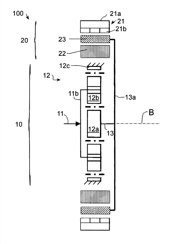
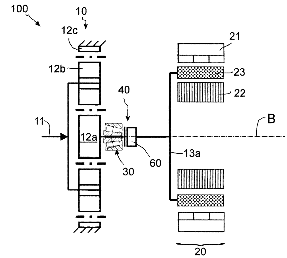
[0029] The electric machine 1 is indicated overall by 100 . In the embodiment shown, it has a planetary gear transmission arrangement 10 and an integrated (magnetic) transmission-generator unit 20 , which combines the function of a magnetic transmission with the generating function of the electric machine stand up.

[0030] The planetary transmission arrangement 10 includes a drive shaft 11 , which drives a planetary transmission stage 12 . The drive shaft 11 is connected via webs 11 b to the planetary gears 12 b of the planetary gear stage 12 . The internal gear 12c is arranged in a rotationally fixed manner, and the sun gear 12a drives the driven shaft 13 .

[0031] The working principle for power generation will now be explained below.

[0032] The electric machine has a fixed secondary part 21 and a fixed primary part 22 . In the exemplary embodiment shown, the secondary part is of separately excited construction, that is to say it is provided with a permanent magnet a...


PUM


Abstract

The inveniton relates to an electrical machine for a wind energy installation. The electrical machine (100) includes a stationary secondary part (21) which is self-excited or externally excited, a stationary primary part (22) with a primary winding element, and a rotatably mounted magnetic modulator, which modulates a magnetic flux density. The magnetic modulator (23) is arranged between the secondary part (21) and the primary part (23) or the primary part (23) is arranged between the secondary part (21) and the magnetic modulator (23).

Description

technical field [0001] The invention relates to an electric machine for a wind energy installation. It should be emphasized, however, that the electric machine can also be advantageously used in other fields and can be used not only as a generator for generating electricity but also as a motor for generating motion. Background technique [0002] Most existing wind energy installations are equipped with fast-rotating generators, in which multistage transmissions are used to convert the relatively slow rotational speed of the wind rotor to the generator rotational speed. In addition, a generator coupled to the wind wheel without a transmission is also used. In order to implement this direct drive concept, the generator is designed as a four-pole slowly rotating permanently excited synchronous machine. [0003] However, this construction leads to a considerable increase in weight compared with a device with a transmission, because the secondary part (rotating part or rotor) o...

Claims


Application Information

Patent Timeline
IPC IPC(8): H02K21/42H02K7/116
CPCH02K7/116H02K7/1838H02K19/24H02K21/42
Inventor I.施塔姆A.瓦特
Owner ROBERT BOSCH GMBH
Why Eureka
Try Eureka