
Rock-soil in-situ testing method

An in-situ test and geotechnical technology, which is applied in the field of foundation soil survey, construction, infrastructure engineering, etc., can solve problems such as costing a lot of manpower and material resources, limited reference value of cone tip resistance, and inability to detect rock and soil mechanical properties, etc. , to achieve the effect of portable testing and flexible operation

Inactive Publication Date: 2021-12-07
ANHUI TRANSPORT CONSULTING & DESIGN INST
View PDF8 Cites 0 Cited by
  • Summary
  • Abstract
  • Description
  • Claims
  • Application Information

AI Technical Summary

Problems solved by technology

In the prior art, for this situation, exploration instruments such as small twist drills, steel drill static exploration, and static penetration testing are mostly used for detection; however, various existing exploration instruments have different problems, among which twist drills can only be used A small amount of rock and soil samples were used for the identification of the soil layer, and the mechanical properties of the rock and soil could not be detected; the penetration rate of the steel drill was artificially pressed in during the penetration process, and the penetration rate was difficult to keep constant. The reference value of the cone tip resistance Ps is limited, and it cannot distinguish the cone tip and cone side resistance; although large-scale exploration instruments such as static penetration and drilling are relatively accurate and have a deep exploration depth, they require a lot of manpower and material resources, exceeding the initial route. The survey depth required by geological survey is usually not used for route geological survey

Method used


Image

  • Rock-soil in-situ testing method
  • Rock-soil in-situ testing method
  • Rock-soil in-situ testing method

Examples


Embodiment Construction

[0032] The structural form of portable geotechnical in-situ testing instrument is set in the present embodiment is:

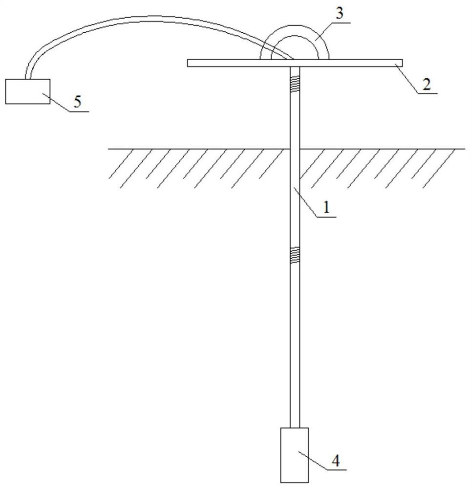
[0033] see figure 1 with figure 2 , the vertical probe rod 1 is connected by the upper lifting member, and the probe 4 is fixedly installed at the bottom of the vertical probe rod 1, and the gas circuit 61 and the counter electrode line 62 drawn in the control box 5 are introduced into the probe 4 through the vertical probe rod 1, and the vertical The probe rod 1 is a hollow steel pipe.

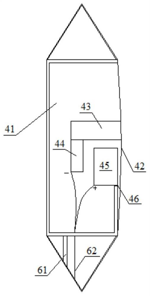
[0034] figure 2 The probe 4 shown is a side pressure probe, and the inner cavity of the probe 4 is a pressure chamber 41 that communicates with the gas path and can be inflated or exhausted. The pressure chamber 41 is composed of three rigid bodies on one side and an elastic diaphragm on one side 42, the elastic diaphragm 42 forms a lateral displacement with the pressure change of the pressure chamber 41, the inner side of the elastic diaphragm 42 is the conductive side, ...


PUM


Abstract

The invention discloses a rock-soil in-situ testing method which is characterized in that a rock-soil in-situ tester is arranged, a probe is fixedly arranged at the bottom of a vertical probe rod, the probe is a lateral pressure probe, and an inner cavity of the probe is a pressure chamber which is communicated with an external gas circuit and can be used for inflation or exhaust control; the pressure chamber consists of rigid bodies on three side surfaces and an elastic membrane on one side surface; the elastic membrane forms lateral displacement along with the pressure change of the pressure chamber; a displacement detection mechanism of the elastic membrane is arranged in the pressure chamber; according to the rock-soil in-situ testing method, the point position pressure of the preset depth is obtained according to the displacement detection signal of the displacement detection mechanism and the pressure signal corresponding to the pressure chamber and used for judging the mechanical property of soil at the preset point position, and point position testing of the preset depth is achieved. The method is particularly suitable for route geological exploration and is used for judging the physical and mechanical properties of rock and soil, thereby providing a basis for engineering construction.

Description

technical field [0001] The invention relates to the technical field of geological exploration, in particular to an in-situ test method for shallow rock and soil suitable for route geological investigation. Background technique [0002] Geological survey is a qualitative and quantitative evaluation of the geological structure and mechanical properties of the project site through survey, surveying, exploration and in-situ testing, and provides geological suggestions for project construction. [0003] In the geological survey of highway routes, it is necessary to ascertain the shallow geological conditions on the route. In the prior art, for this situation, exploration instruments such as small twist drills, steel drill static exploration, and static penetration testing are mostly used for detection; however, various existing exploration instruments have different problems, among which twist drills can only be used A small amount of rock and soil samples were used for the iden...

Claims


Application Information

Patent Timeline
Patent Type & Authority Applications(China)
IPC IPC(8): E02D1/00
CPCE02D1/00
Inventor 石川张志峰李翻翻温广军吴磊磊李昊煜陈星
Owner ANHUI TRANSPORT CONSULTING & DESIGN INST
Learn More