
LED illumination module, rated output current setting method of LED driving power supply and vehicle lamp

A technology of LED driving and LED lighting, which is applied in the direction of electrical components, etc., can solve the problems affecting the lighting effect, achieve the effect of maintaining the lighting effect, stabilizing the lighting effect, and increasing the available power

Pending Publication Date: 2021-12-07
HASCO VISION TECHNOLOGY CO LTD
View PDF0 Cites 0 Cited by
  • Summary
  • Abstract
  • Description
  • Claims
  • Application Information

AI Technical Summary

Problems solved by technology

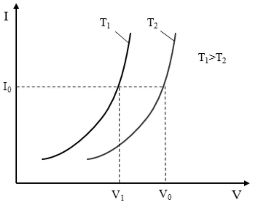
[0003] At present, the LED light source on the car lamp uses an LED constant current drive power supply. The rated output current of the LED constant current drive power supply is set according to the volt-ampere characteristic curve of the LED light source at low temperature. The LED light source corresponding to the volt-ampere characteristic curve The output power of the LED light source is the rated power of the LED light source. The low temperature is like the working environment temperature when the LED light source is initially started, and the volt-ampere characteristic curve of the LED light source will shift to the left as the temperature increases, and the LED light source on the car light is stable. The actual working environment temperature during work is much higher than this low temperature. When the current of the LED constant current drive power supply is constant, according to the volt-ampere characteristic curve of the LED light source that shifts to the left after the temperature rises, the LED constant current drive power supply to the LED The driving voltage output by the light source (the voltage that drives the LED light source) drops significantly, then the output power of the LED light source at this time will be much smaller than the output power of the LED light source at low temperature, that is, the rated power of the LED light source, which will seriously affect the lighting effect
[0004] like figure 1 Shown, T 2 It is the ambient temperature when setting or calculating the rated output current of the LED constant current drive power supply. Generally, it is the lower temperature when the LED light source is just turned on. At the temperature T 2 The driving voltage output from the lower LED constant current driving power supply to the LED light source is V 0 , according to V 0 Calculate the drive current as I 0 , and put I 0 Set as the rated output current of the LED constant current drive power supply, the rated output current is the current that the LED light source can work continuously under the rated environmental conditions, the current in normal operation should not exceed the rated output current, then the rated output current at this time Power is P 0 = I 0 ·V 0 , with the increase of LED working time, the LED light source enters a stable working state, and the working environment temperature changes from T 2 raised to T 1 , at this time, the driving voltage output from the LED constant current driving power supply to the LED light source is determined by V 0 reduced to V 1 , but the driving current has reached the maximum value, that is, the driving current can no longer be increased, and it is still I 0 , so it is impossible to increase the output power of the LED light source by increasing the driving current and simultaneously increasing the driving voltage. Therefore, if figure 2 As shown, the output power of the LED light source at this time is P 1 = I 0 ·V 1 , while V 1 0 , so the output power of the LED after entering the stable working state is actually reduced, and the reduction is relatively large, resulting in a greatly reduced lighting effect

Method used


Image

  • LED illumination module, rated output current setting method of LED driving power supply and vehicle lamp
  • LED illumination module, rated output current setting method of LED driving power supply and vehicle lamp
  • LED illumination module, rated output current setting method of LED driving power supply and vehicle lamp

Examples


Embodiment Construction

[0023] The specific implementation manners of the embodiments of the present invention will be described in detail below in conjunction with the accompanying drawings. It should be understood that the specific implementation manners described here are only used to illustrate and explain the embodiments of the present invention, and are not intended to limit the embodiments of the present invention.

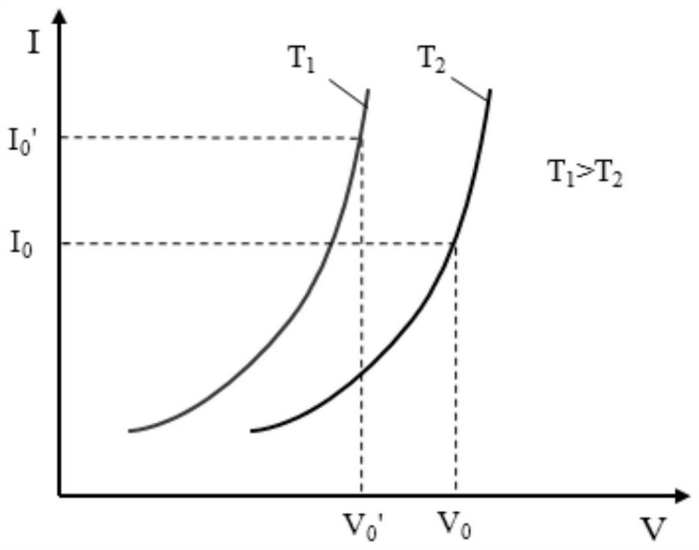
[0024] Such as image 3 with Figure 4 As shown, an embodiment of the LED lighting module of the present invention includes an LED light source and an LED driving power supply. The LED driving power supply supplies power to the LED light source. It is assumed that the LED light source has a first ambient temperature T when it works stably. 1 , other working conditions have the second ambient temperature T 2 ,T 1 >T 2 ; The LED driving power supply is at the first ambient temperature T 1 The first drive voltage output to the LED light source is V 0 ', through the first ambient ...


PUM


Abstract

The invention belongs to the field of vehicle lamplight, and discloses an LED illumination module, a rated output current setting method of an LED driving power supply, a vehicle lamp and a vehicle. The LED illumination module comprises an LED light source and the LED driving power supply, the LED driving power supply supplies power to the LED light source, and the LED light source has a first environment temperature T1 when working stably and has a second environment temperature T2 in other working states, and T1 is larger than T2. The LED driving power supply outputs a first driving voltage V0' to the LED light source at the first environment temperature T1 and obtains a corresponding first driving current I0 ' from the V0', and the first driving current I0 ' is set as a rated output current of the LED driving power supply. According to the invention, the output power of an LED in a stable working state at the higher environment temperature is improved, namely the output power of the LED light source can be basically kept unchanged in a full temperature range, so that the illumination performance of the LED light source can be fully exerted, and a stable illumination effect can be maintained.

Description

technical field [0001] The invention relates to an LED lighting module, a method for setting the rated output current of an LED driving power supply, a car lamp and a vehicle, and belongs to the field of car lamps. Background technique [0002] In recent years, LED light sources have become the main force of automotive lighting systems due to their advantages such as high luminous efficiency, small luminous area, low energy consumption, low manufacturing cost, and long life, and are favored by more and more automobile manufacturers and consumers. [0003] At present, the LED light source on the car lamp uses an LED constant current drive power supply. The rated output current of the LED constant current drive power supply is set according to the volt-ampere characteristic curve of the LED light source at low temperature. The LED light source corresponding to the volt-ampere characteristic curve The output power of the LED light source is the rated power of the LED light sour...

Claims


Application Information

Patent Timeline
IPC IPC(8): H05B45/345H05B45/30
CPCH05B45/345H05B45/30
Inventor 李志兵陈兆禹
Owner HASCO VISION TECHNOLOGY CO LTD
Learn More