
A level bubble debugging device for laser collimation equipment

A technology of laser alignment and level bubble, which is applied in the direction of active optical measuring devices, mechanical equipment, measuring devices, etc., can solve the problems of manual adjustment error, high adjustment difficulty, laser alignment error, etc., and achieve good clamping effect and guarantee The effect of the collimation effect

Active Publication Date: 2022-02-22
临沂朝日电子有限公司
View PDF5 Cites 0 Cited by
  • Summary
  • Abstract
  • Description
  • Claims
  • Application Information

AI Technical Summary

Problems solved by technology

[0003] The level bubble debugging device of the existing laser collimation equipment has the following technical defects: First, because the laser collimation equipment is applied to different terrains and scenes, there will be situations where the ground is inclined and uneven, and then the laser collimation equipment needs to be manually adjusted If there is a large error in laser alignment, the quality of the project will not pass; second, if the fine-tuning motor is used to control the angle correction of the laser alignment, fine-tuning When the motor is working, the high vibration frequency has a bad influence on the correction, which leads to low correction accuracy and cannot be applied to the collimation operation that requires high precision.

Method used


Image

  • A level bubble debugging device for laser collimation equipment
  • A level bubble debugging device for laser collimation equipment
  • A level bubble debugging device for laser collimation equipment

Examples


Embodiment Construction

[0044] The following will clearly and completely describe the technical solutions in the embodiments of the present invention with reference to the accompanying drawings in the embodiments of the present invention. Obviously, the described embodiments are only some, not all, embodiments of the present invention. Based on the embodiments of the present invention, all other embodiments obtained by persons of ordinary skill in the art without making creative efforts belong to the protection scope of the present invention.

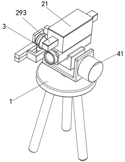
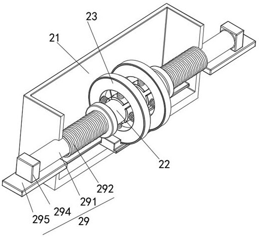
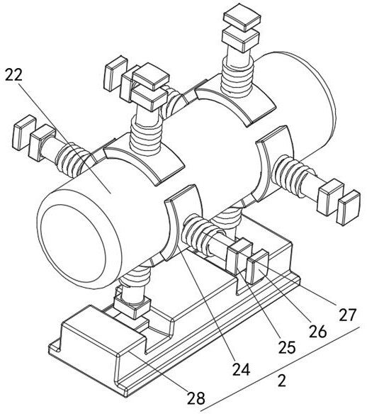
[0045] see Figure 1-7 , a level bubble debugging device for laser collimation equipment, including a tripod 1, a debugging device 2, a laser collimator 3, an anti-motion device 4, a shock absorbing device 5 and a measuring device 6, and the upper side of the tripod 1 is movable and installed There is a laser collimator 3, a debugging device 2 is fixedly installed on the upper side of the laser collimator 3, an anti-motion device 4 is arranged on the right sid...


PUM


Abstract

The invention discloses a level bubble debugging device for laser collimation equipment, and relates to the technical field of laser collimation equipment. The upper side of the laser collimator is fixedly connected with a rectangular shell, and the inner bottom side of the rectangular shell slides A sliding block is connected, the upper side of the sliding block is fixedly connected with a ring box, the inner axial outer wall of the ring box is fixedly connected with a first coil, and the first coil is provided with a magnetic A clamping block is fixedly connected to the inner side of the magnetic block with respect to the axial direction of the ring box, and the first spring is sleeved on the axial outer side of the clamping block. The level bubble debugging device of the laser alignment equipment, through the cooperation between the first sliding rheostat, the first coil, the magnetic block and the clamping block, realizes the size of the offset of the center of gravity and the clamping force of the clamping block. The size of the vial changes in a positive direction, so as to achieve a better clamping effect. At the same time, the vial is not fixedly connected with the structure, so as to achieve the purpose of convenient replacement.

Description

technical field [0001] The invention relates to the technical field of laser collimation equipment, in particular to a vial debugging device for laser collimation equipment. Background technique [0002] The level bubble measures the inclination angle with the horizontal plane through the deviation distance between the internal bubble and the center. The laser collimator uses the laser beam as a directional emission and forms a beam in space as the collimation datum line, and then carries out the project Measurement and calibration. [0003] The level bubble debugging device of the existing laser collimation equipment has the following technical defects: First, because the laser collimation equipment is applied to different terrains and scenes, there will be situations where the ground is inclined and uneven, and then the laser collimation equipment needs to be manually adjusted If there is a large error in laser alignment, the quality of the project will not pass; second, ...

Claims


Application Information

Patent Timeline
Patent Type & Authority Patents(China)
IPC IPC(8): G01C15/00G01C9/24F16M11/10F16M11/18
CPCG01C15/002G01C9/24F16M11/10F16M11/18
Inventor 朱中林刘鲁子
Owner 临沂朝日电子有限公司
Learn More