
Valve airtightness test bench

A technology of air tightness and test bench, which is applied in fluid tightness testing, liquid tightness measurement using liquid/vacuum degree, machine/structural component testing, etc. It can solve problems such as difficulty in valve air tightness testing, Achieve the effects of improving judgment efficiency, simple equipment operation, and avoiding difficult operation

Pending Publication Date: 2021-12-17
ANHUI TUNXI HIGH PRESSURE VALVE
View PDF0 Cites 0 Cited by
  • Summary
  • Abstract
  • Description
  • Claims
  • Application Information

AI Technical Summary

Problems solved by technology

[0003] The purpose of the present invention is to overcome the deficiencies of the prior art and provide a valve airtightness test bench to solve the technical problem of difficult valve airtightness testing in the prior art

Method used


Image

  • Valve airtightness test bench
  • Valve airtightness test bench

Examples


Embodiment

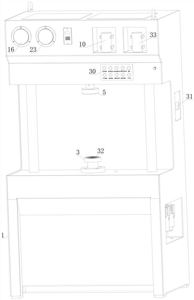
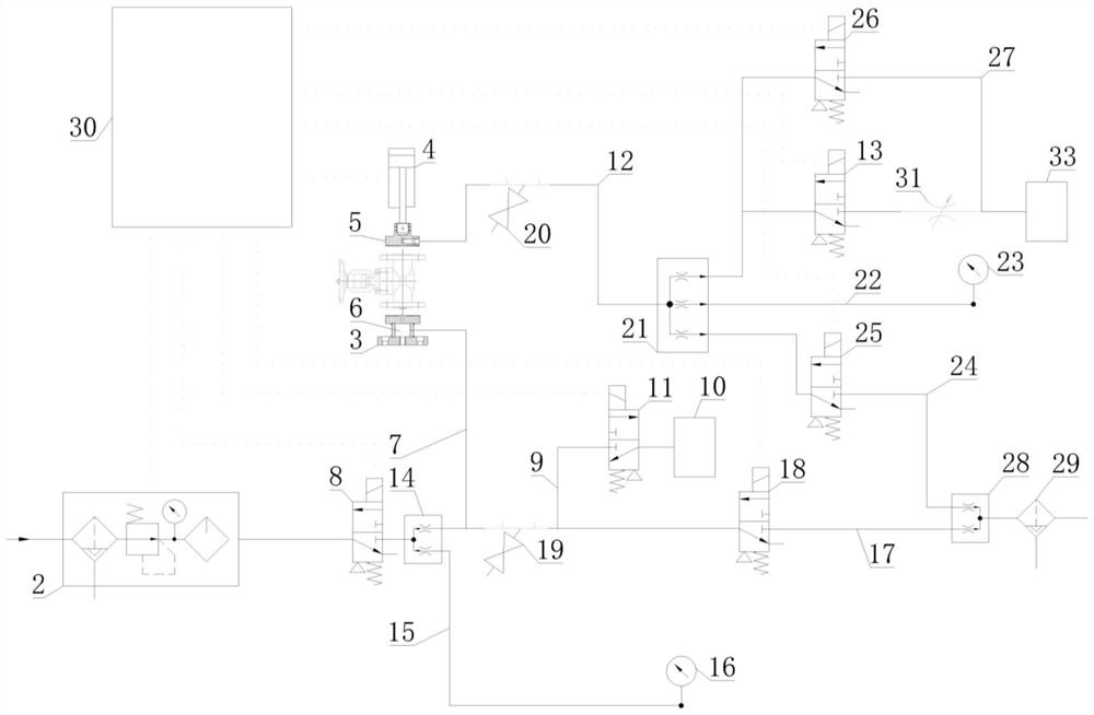
[0022] combined with figure 1 and 2 , this embodiment provides a valve airtightness test bench, including a bench body 1, and the structure of the bench body 1 can be various, as long as the functional requirements are met. In this example, combined with the figure 1 In this embodiment, the stand body 1 is specifically a cuboid cabinet-like structure, and a recessed gap is provided on the front surface of the middle part, and the bottom of the gap is a horizontal operating surface, so as to facilitate equipment operation in it. In this embodiment, the sides are respectively provided with columns for supporting and connecting the upper and lower ends thereof, so as to achieve the purpose of supporting;


PUM


Abstract

The invention discloses a valve airtightness test bench, which relates to a detection device and comprises a bench body. An air source device is fixedly mounted in the bench body, a first pressing block and a driving structure are fixedly mounted on the air source device, and a second pressing block capable of being driven by the driving structure to linearly reciprocate relative to the first pressing block is fixedly mounted at the action end of the driving structure. Air holes are formed in the first pressing block and the second pressing block respectively, the air holes in the first pressing block are connected with an air source device through a first guide pipe, a normally-closed first two-position three-way electromagnetic valve is installed on the first guide pipe, and a first airflow observation device is further communicated with the portion, between the first two-position three-way electromagnetic valve and the corresponding air holes, of the first guide pipe through a second guide pipe. A normally-closed second two-position three-way electromagnetic valve is further installed on the second guide pipe, an air hole in the second pressing block is connected with a second airflow observation device through a third guide pipe, and a third two-position three-way electromagnetic valve is installed on the third guide pipe. Valve airtightness detection can be effectively carried out.

Description

technical field [0001] The invention relates to a detection device, in particular to a valve air tightness test device. Background technique [0002] Before the valve leaves the factory, it needs to test its air sealing parameters, and the valve can only leave the factory after the test valve has no leakage. At present, most of the existing equipment has complicated structure, cumbersome operation, and many testing links. It is difficult for operators to get started, and the work efficiency is low, which makes it extremely difficult to test a large number of valves, especially the air tightness test. Contents of the invention [0003] The purpose of the present invention is to overcome the deficiencies of the prior art, and provide a valve airtightness test bench to solve the technical problem of difficult valve airtightness test in the prior art. [0004] The present invention is achieved through the following technical solutions: [0005] A valve airtightness test benc...

Claims


Application Information

Patent Timeline
IPC IPC(8): G01M3/28
CPCG01M3/2876
Inventor 钱勇吴尖斌李煜吴健晖毕靖锋吴朝阳单彤彤
Owner ANHUI TUNXI HIGH PRESSURE VALVE
Learn More