
Butt joint structure and butt joint method for extra-high voltage bushing and lead device of converter transformer

A UHV and commutation technology, applied in the field of transformers, can solve problems such as other structural damage, inability to align at one time, size deviation, etc., achieve precise alignment, eliminate deviation and damage, and improve installation quality and efficiency Effect

Pending Publication Date: 2021-12-17
魏德曼电力绝缘科技(嘉兴)有限公司 +4
View PDF0 Cites 0 Cited by
  • Summary
  • Abstract
  • Description
  • Claims
  • Application Information

AI Technical Summary

Problems solved by technology

[0002] In high-voltage transformers, the connection position between the converter UHV bushing and the lead device is 2-3 meters away from the end of the lead device, and there are often many insulating paper tubes and other structures arranged around the connection position. When installing on the lead device, the bushing is usually blindly inserted into the lead device based on the experience of the installer. Since the butt joint position is deep inside and cannot be seen, it is often not possible to align it at one time during the installation process, and dimensional deviations often occur, colliding with the butt joint. Other structures around the position often damage or damage other structures, which affects the quality, delivery time and cost of converter UHV bushings and lead devices

Method used


Image

  • Butt joint structure and butt joint method for extra-high voltage bushing and lead device of converter transformer
  • Butt joint structure and butt joint method for extra-high voltage bushing and lead device of converter transformer
  • Butt joint structure and butt joint method for extra-high voltage bushing and lead device of converter transformer

Examples


Embodiment Construction

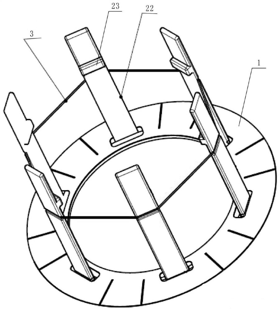
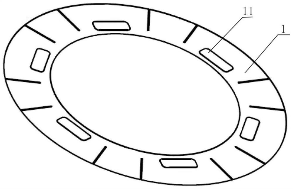
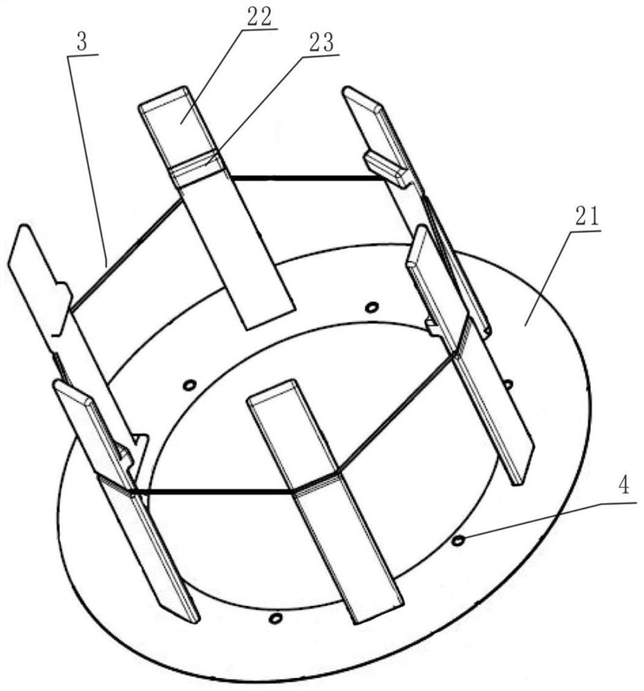
[0011] see Figure 1 to Figure 3 , the butt joint structure of the UHV bushing of the converter and the lead wire device includes an insulating cardboard 1 and a bracket, both of which are insulated. The insulating cardboard 1 is in the shape of a ring-shaped plate with a central hole in the middle and is made of insulating paper. This insulating material is commonly used in transformers and is often used as shielding insulation for transformers. The insulating cardboard 1 is provided with six rectangular through-holes 11, and the six through-holes 11 are evenly arranged along the circumferential direction of the insulating cardboard 1. The distance from each through-hole 11 to the central axis of the insulating cardboard 1 is equal, and two adjacent The included angle formed by the through hole 11 and the central axis of the insulating cardboard 1 is equal. The insulating cardboard 1 has good insulating performance, and can effectively shield the electric strength of AC and ...


PUM


Abstract

The invention relates to a butt joint structure and a butt joint method for an extra-high voltage bushing and a lead device of a converter transformer. The butt joint structure comprises an insulating paperboard and a support, the insulating paperboard is in an annular plate shape, a plurality of through holes are formed in the insulating paperboard, the support comprises a bottom plate and a plurality of guide plates, the bottom plate is in an annular plate shape, the insulating paperboard is placed on the bottom plate, the guide plates extend from the bottom plate to one side, the guide plates penetrate through the through holes in the insulating cardboard, the guide plates correspond to the through holes one to one, the guide plates are evenly arranged in the circumferential direction of the bottom plate, and positioning protrusions are arranged on the inner wall faces of the guide plates. The butt joint structure has alignment and guiding effects on the sleeve, the positioning protrusion has a butt joint completion indication effect, it can be guaranteed that in the process that the sleeve is installed on the wire leading device, accurate alignment can be achieved, deviation and bumping damage caused when the sleeve is installed on the wire leading device can be reduced or eliminated, the sleeve and the wire leading device are assembled at a time without errors, and the mounting quality and efficiency are improved.

Description

technical field [0001] The invention relates to the technical field of transformers, in particular to a butt joint structure and a butt joint method of a converter transformer UHV bushing and a lead wire device. Background technique [0002] In high-voltage transformers, the connection position between the converter UHV bushing and the lead device is 2-3 meters away from the end of the lead device, and there are often many insulating paper tubes and other structures arranged around the connection position. When installing on the lead device, the bushing is usually blindly inserted into the lead device based on the experience of the installer. Since the butt joint position is deep inside and cannot be seen, it is often not possible to align it at one time during the installation process, and dimensional deviations often occur, colliding with the butt joint. Other structures around the location often damage or damage other structures, which affects the quality, delivery time a...

Claims


Application Information

Patent Timeline
Patent Type & Authority Applications(China)
IPC IPC(8): H01F27/32H01F27/29H01F41/00
CPCH01F27/32H01F27/29H01F41/00
Inventor 单英玉刘晨肖烈龚慧刘鑫李金忠王琳孙建涛张书琦程涣超遇心如张磊周家斌杨仁毅叶壮壮巩跟盼刘科良
Owner 魏德曼电力绝缘科技(嘉兴)有限公司
Learn More