
Synchronous rectifier shutdown control circuit and synchronous rectification control circuit

A technology for turning off control circuits and synchronous rectifier tubes, applied in control/regulation systems, high-efficiency power electronic conversion, DC power input conversion to DC power output, etc., can solve the problem of LLC resonant converter conversion efficiency decline, detection threshold drift, It is difficult to accurately detect problems such as current zero crossing to achieve the effect of reducing circuit power consumption

Active Publication Date: 2020-08-25
CHENGDU MONOLITHIC POWER SYST
View PDF11 Cites 0 Cited by
  • Summary
  • Abstract
  • Description
  • Claims
  • Application Information

AI Technical Summary

Problems solved by technology

However, in the application of high current (for example, the peak-to-peak value of the inductor current of the LLC resonant converter reaches 45A~90A), the current slew rate (ie: current change rate) flowing through the synchronous rectifier is very high (for example, it can reach 1A~3A / ns), it is difficult to accurately detect the zero-crossing of the current flowing through the synchronous rectifier (for example, the zero-crossing detection threshold drifts due to the input offset voltage of the zero-crossing detection comparator)
Regardless of whether the detected synchronous rectifier current zero-crossing time lags behind or advances the synchronous rectifier current's actual zero-crossing time, it will lead to a decrease in the conversion efficiency of the LLC resonant converter.

Method used


Image

  • Synchronous rectifier shutdown control circuit and synchronous rectification control circuit
  • Synchronous rectifier shutdown control circuit and synchronous rectification control circuit
  • Synchronous rectifier shutdown control circuit and synchronous rectification control circuit

Examples


Embodiment Construction

[0023] Specific embodiments of the present disclosure will be described in detail below, and it should be noted that the embodiments described here are only for illustration, and are not intended to limit the present disclosure. On the contrary, the disclosure is intended to cover various alternatives, modifications and equivalents as defined within the spirit and scope of the disclosure as defined by the appended claims. In the following description, numerous specific details are set forth in order to provide a thorough understanding of the present disclosure. However, it will be understood by those of ordinary skill in the art that the present disclosure may be practiced without these specific details. In some other embodiments, well-known schemes, processes, components, circuits or methods are not described in detail in order to highlight the gist of the present disclosure.

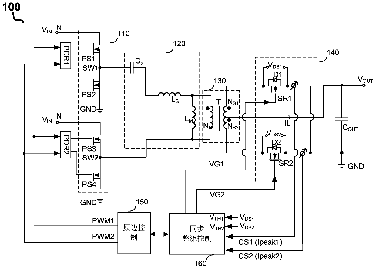
[0024] figure 1 A schematic diagram of the circuit architecture of the LLC resonant converter 100...


PUM


Abstract

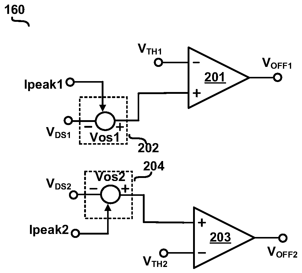
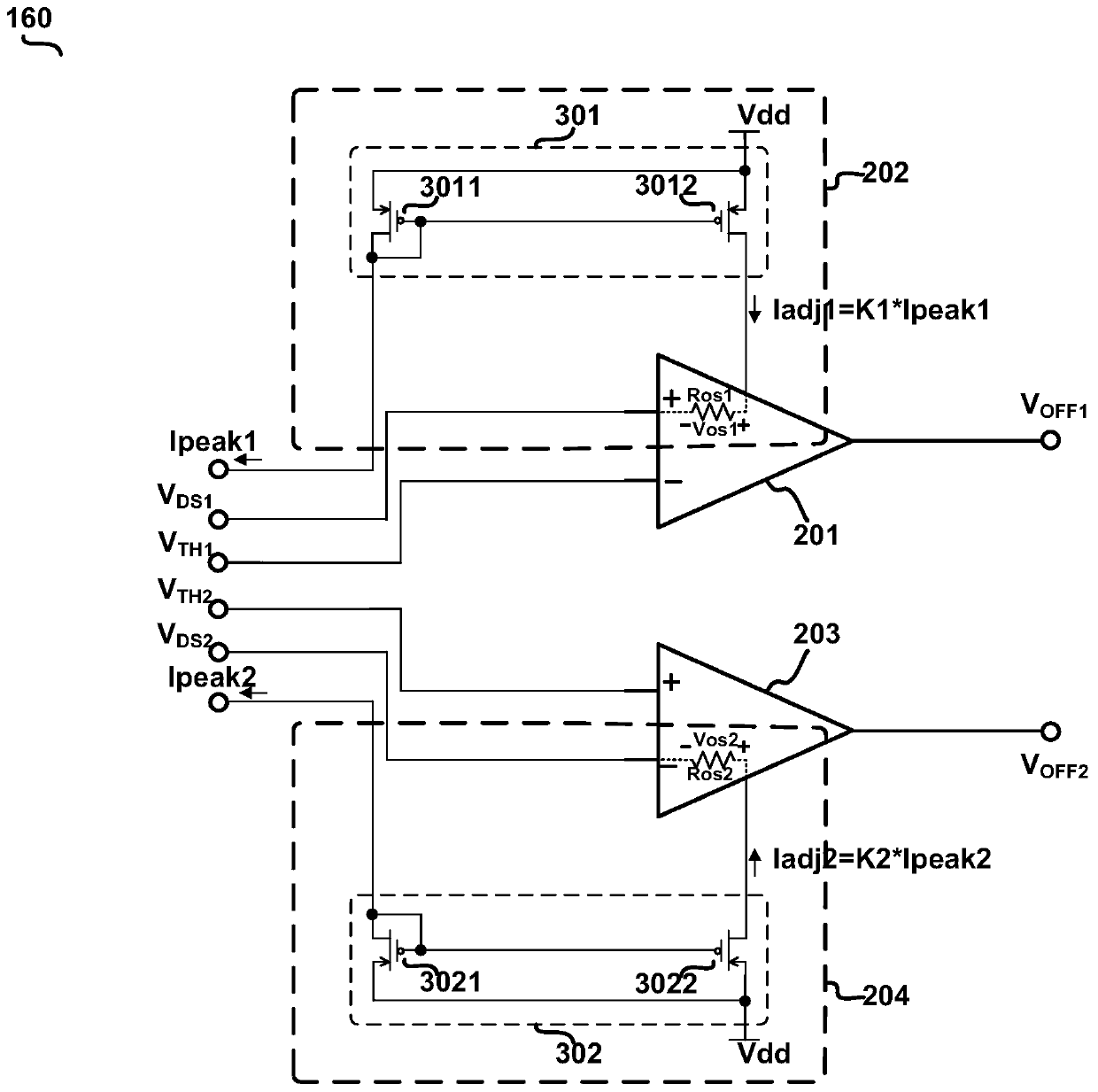
The invention discloses a synchronous rectification tube shutdown control circuit and a synchronous rectification control circuit. The turn-off control circuit of the synchronous rectifier can receive / detect the drain-source voltage signal representing the drain-source voltage of the synchronous rectifier and the zero-crossing threshold, and compare the drain-source voltage signal with the zero-crossing threshold to determine the current flow through the synchronous rectifier. Whether the current of the synchronous rectifier is zero-crossing, and receiving a current peak detection signal representing the peak value of the current flowing through the synchronous rectifier, adjusting the amplitude of the zero-crossing threshold based on the current peak detection signal to follow the current passing through the synchronous rectifier The peak value of the current changes in the same direction, and the signal representing the conduction time of the body diode when the synchronous rectifier is turned off can also be received, and the zero-crossing can be adjusted based on the conduction time of the body diode when the synchronous rectifier is turned off. threshold. In this way, the turn-off moment of the synchronous rectifier can be controlled more precisely, thereby reducing the power consumption of the circuit.

Description

technical field [0001] The disclosed embodiments of the present invention relate to an electronic circuit, in particular to an LLC resonant converter and a synchronous rectifier control circuit thereof. Background technique [0002] LLC resonant converters often use synchronous rectifiers instead of ordinary diodes in order to reduce circuit losses in many high-current applications. When it is detected that the current flowing through the synchronous rectifier crosses zero, the synchronous rectifier is controlled to be turned off. However, in the application of high current (for example, the peak-to-peak value of the inductor current of the LLC resonant converter reaches 45A~90A), the current slew rate (ie: current change rate) flowing through the synchronous rectifier is very high (for example, it can reach 1A~3A / ns), it is difficult to accurately detect the zero-crossing of the current flowing through the synchronous rectifier (for example, the zero-crossing detection th...

Claims


Application Information

Patent Timeline
Patent Type & Authority Patents(China)
IPC IPC(8): H02M3/335H02M1/088
CPCH02M1/088H02M3/33592H02M1/0058Y02B70/10H02M1/083H02M1/0009
Inventor 张天柱
Owner CHENGDU MONOLITHIC POWER SYST
Learn More