
Cement paving device for building

A technology for cement installation and construction, which is applied in cement mixing installations, buildings, building structures, etc., can solve the problems of easy falling, uneven cement paving, and reduced wall laying efficiency, and achieve the effect of avoiding solidification.

Pending Publication Date: 2021-12-21
陆爱珍
View PDF8 Cites 0 Cited by
  • Summary
  • Abstract
  • Description
  • Claims
  • Application Information

AI Technical Summary

Problems solved by technology

[0005] In order to overcome the disadvantages that the cement is easy to drop when shoveling the cement onto the bricks, causing waste, and the cement is not uniform enough to reduce the efficiency of building walls, the technical problem of the present invention is to provide a No drop during the process of laying on the block, less waste, more uniform cementing device for construction

Method used


Image

  • Cement paving device for building
  • Cement paving device for building
  • Cement paving device for building

Examples


Embodiment 1

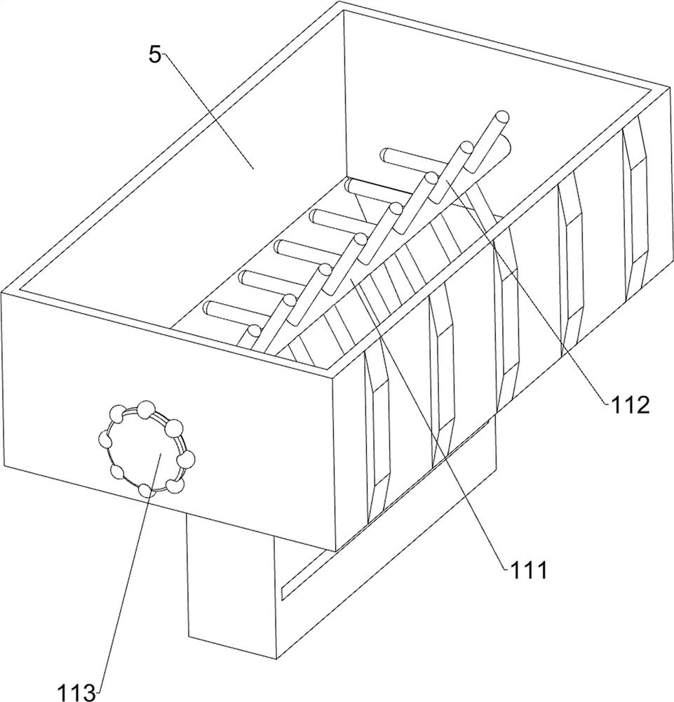
[0027] A cement paving device for construction, such as Figure 1-9 As shown, it includes a base 1, a guide rod 2, a sliding sleeve 3, a first mounting block 4, a hopper 5, a baffle plate 6, a driving mechanism 7 and a lifting mechanism 8, and the front and rear parts of the base 1 are provided with guide rods 2, and the guide rods Sliding sleeves 3 are provided on the rod 2, first mounting blocks 4 are provided on the sliding sleeves 3, a hopper 5 is provided between the front and rear first mounting blocks 4, and a hopper 5 is provided between the right parts of the two guide rods 2. There is a baffle 6, and the baffle 6 is slidingly matched with the hopper 5. The base 1 is provided with a driving mechanism 7, and the base 1 is provided with a lifting mechanism 8.

[0028] When using the device, the staff moves the equipment to the bricks where cement needs to be laid, and then the staff pours the mixed concrete into the hopper 5. After completion, the staff drives the hoppe...

Embodiment 2

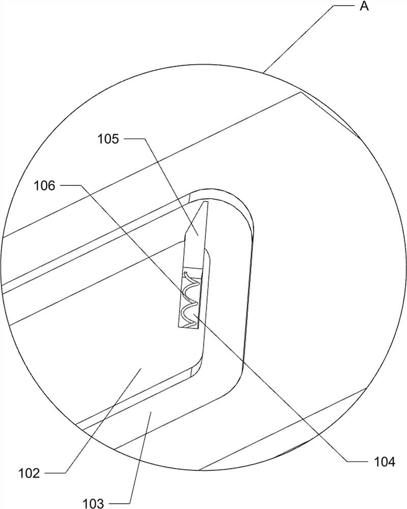
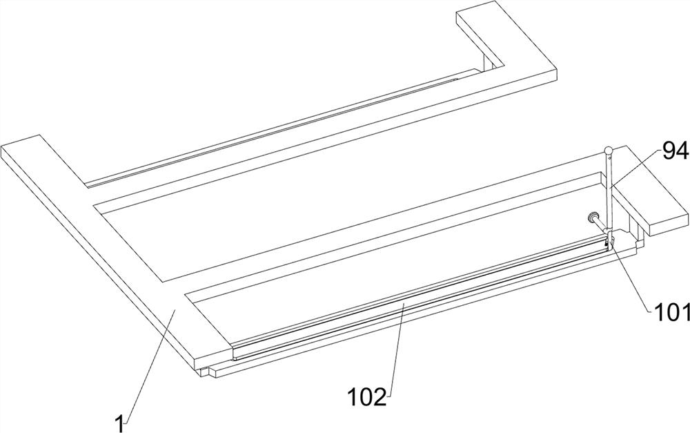
[0034]On the basis of Example 1, such as figure 1 , Figure 4 and Figure 5 As shown, also includes clamping mechanism 9, and clamping mechanism 9 includes the 3rd mounting block 91, cross bar 92, second spring 93, L shape bar 94 and fixing block 95, all is provided with on the first mounting block 4 The third mounting block 91, the third mounting block 91 is provided with a cross bar 92, the cross bar 92 is slidably provided with an L-shaped bar 94, and a second spring is wound between the L-shaped bar 94 and the cross bar 92 93, the lower part of the L-shaped bar 94 is provided with a fixed block 95.

[0035] When using this device, the staff pulls the L-shaped bar 94 to slide outward on the cross bar 92, the second spring 93 is deformed, and the outward sliding of the L-shaped bar 94 drives the fixed block 95 to move outwards and no longer clamps the brick. , the staff fixes the L-shaped rod 94 with a tool, and when the hopper 5 moves to the left to a certain distance, t...


PUM


Abstract

The invention relates to a cement paving device, and particularly relates to a cement paving device for a building. The cement paving device for the building is provided, cement cannot fall off in the process of shoveling the cement onto bricks, waste is reduced, and the cement is paved more uniformly. The cement paving device for the building comprises a base, two guide rods, two sliding sleeves and two first mounting blocks, wherein the two guide rods are mounted on the base; the two sliding sleeves are slidably mounted on the guide rods; and the two first mounting blocks are mounted on the sliding sleeves. According to the cement paving device for the building, power can be provided through a driving mechanism during cement paving, strip-shaped blocks can be automatically moved upwards through a lifting mechanism when the base is moved, and the paved cement is prevented from being scraped away; the base can be moved leftwards through a clamping mechanism after the cement is paved, and manual pushing is not needed any more; the cement in a hopper can be stirred through a manual stirring mechanism, and the cement is prevented from being solidified; and the cement in the hopper can be automatically stirred through an automatic stirring mechanism.

Description

technical field [0001] The invention relates to a cement laying device, in particular to a cement laying device for construction. Background technique [0002] When building a wall, it is necessary to spread a layer of cement on the bricks, and then put the next brick on top of the laid cement to build the wall. [0003] At present, when laying cement, the cement is usually installed in small buckets manually, and then the cement is shoveled to the bricks by the shovel used for building the wall, and then the cement is paved. In the way of paving on the bricks, the cement is easy to fall during the process of shoveling onto the bricks, thus causing waste. wall efficiency. [0004] Therefore, be badly in need of researching and developing a kind of process that cement is shoveled to brick and can not drop, reduce waste, and more uniform building cement paving device when paving cement solves the above problems. Contents of the invention [0005] In order to overcome the ...

Claims


Application Information

Patent Timeline
Patent Type & Authority Applications(China)
IPC IPC(8): E04F21/08E04F21/18B28C5/14B28C5/08B28C5/44
CPCE04F21/08E04F21/18B28C5/14B28C5/0806B28C5/44
Inventor 陆爱珍
Owner 陆爱珍
Learn More