
An anti-return air intake structure for a rotary detonation combustion chamber

A technology of air intake structure and combustion chamber, which is applied in the field of aero-engines, can solve the problems of large total pressure loss in the combustion chamber, and achieve the effect of increasing the total pressure gain and reducing the impact on performance

Active Publication Date: 2022-07-26
AIR FORCE UNIV PLA
View PDF6 Cites 0 Cited by
  • Summary
  • Abstract
  • Description
  • Claims
  • Application Information

AI Technical Summary

Problems solved by technology

[0005] In order to improve the problem of the large total pressure loss of the combustion chamber caused by the pressure return, the application provides an anti-backward intake structure for the rotating detonation combustion chamber

Method used


Image

  • An anti-return air intake structure for a rotary detonation combustion chamber
  • An anti-return air intake structure for a rotary detonation combustion chamber
  • An anti-return air intake structure for a rotary detonation combustion chamber

Examples


Embodiment 1

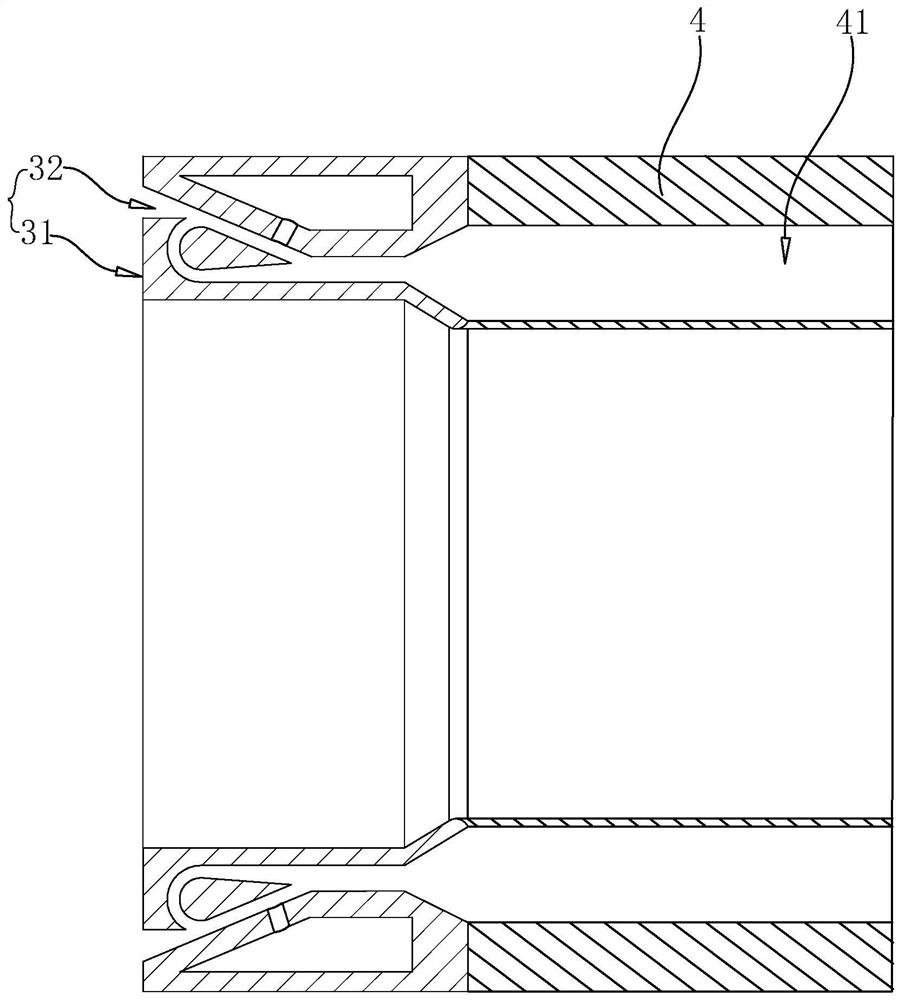
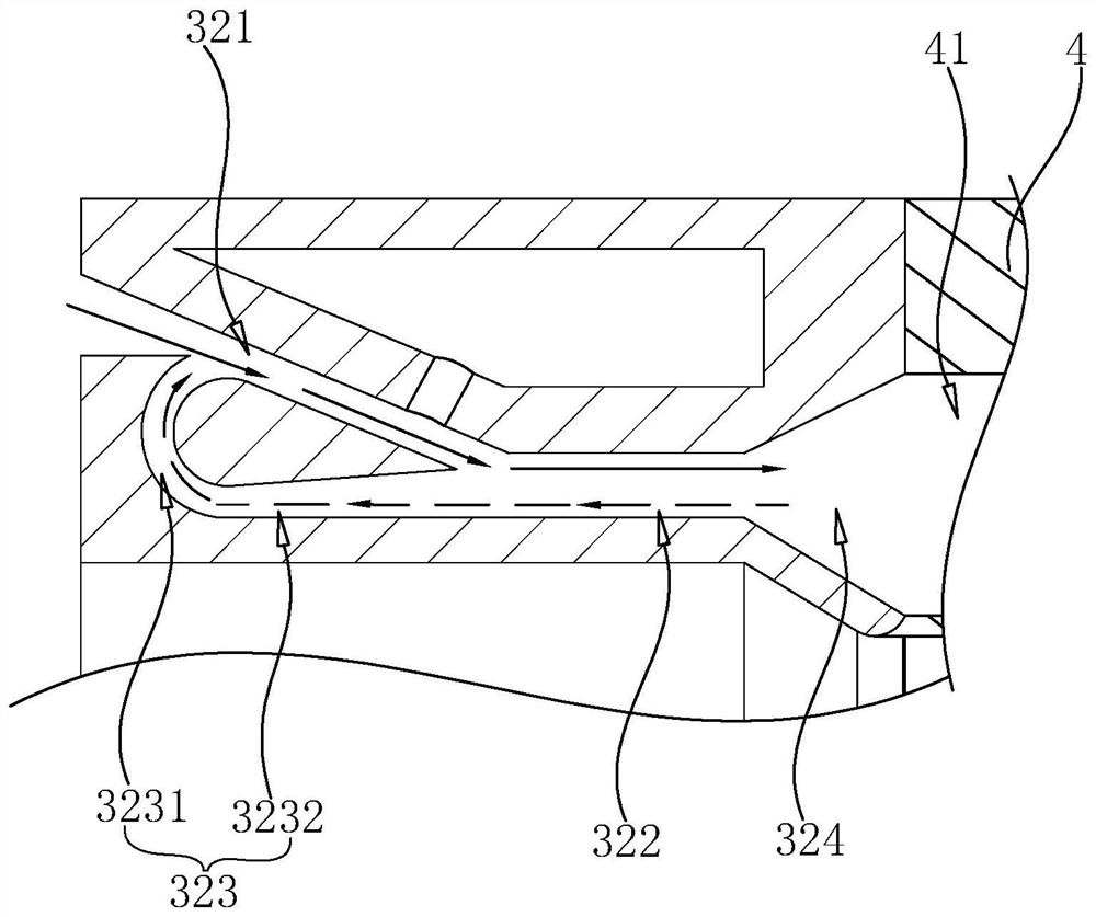
[0041] like figure 2 As shown, a rotary detonation combustion chamber anti-return air intake structure includes a Tesla valve 3 that communicates with the rotary detonation combustion chamber 4 and is snap-fitted at the inlet of the rotary detonation combustion chamber 4 . The Tesla valve 3 includes a casing 31 and a flow channel 32. The casing 31 is coaxially clamped to the outer wall of the rotary detonation combustion chamber 4. The flow channel 32 is opened in the casing 31, and the inlet end of the flow channel 32 is used for introducing air. , the outlet end of the flow channel 32 communicates with the annular channel 41 of the rotary detonation combustion chamber 4 .

[0042] like figure 2 , image 3 As shown, the flow channel 32 includes an intake channel 321, a connecting channel 322, an arc-shaped return channel 323 and an expansion channel 324; one end of the intake channel 321 is used to introduce air, and the other end communicates with the connecting channel ...

Embodiment 2

[0055] like Figure 8 , Figure 9 As shown, the difference between this embodiment and Embodiment 1 is that the housing 31 includes a first connection cylinder 311, a second connection cylinder 312 and a flow guide block 313, and the first connection cylinder 311 is coaxially sleeved on the second connection cylinder 311. Inside the barrel 312 , the guide block 313 is coaxially fixed between the first connecting barrel 311 and the second connecting barrel 312 .

[0056] The implementation principle of Embodiment 2 is the same as that of Embodiment 1, and details are not repeated here.


PUM


Abstract

The present application relates to an anti-return air intake structure for a rotary detonation combustion chamber, which includes a Tesla valve communicated with the rotary detonation combustion chamber and disposed at the inlet of the rotary detonation combustion chamber, the Tesla valve comprising a housing and a flow channel, the casing is coaxially connected to the outer wall of the rotary detonation combustion chamber, the flow channel is arranged in the casing, the inlet end of the flow channel is used for introducing air, and the outlet end of the flow channel is connected to the The annular channel of the rotary detonation combustion chamber communicates with each other. The present application utilizes the one-way flow characteristic of the Tesla valve to separate the forward passage of air and fuel into the rotary detonation combustion chamber and the reverse passage of pressure return, effectively reducing the pressure return to the forward entry. The obstacle of the air and fuel, so that the knocking boost can make up for the total pressure loss caused by the upper intake air, thereby improving the total pressure gain of the rotary knocking combustion chamber.

Description

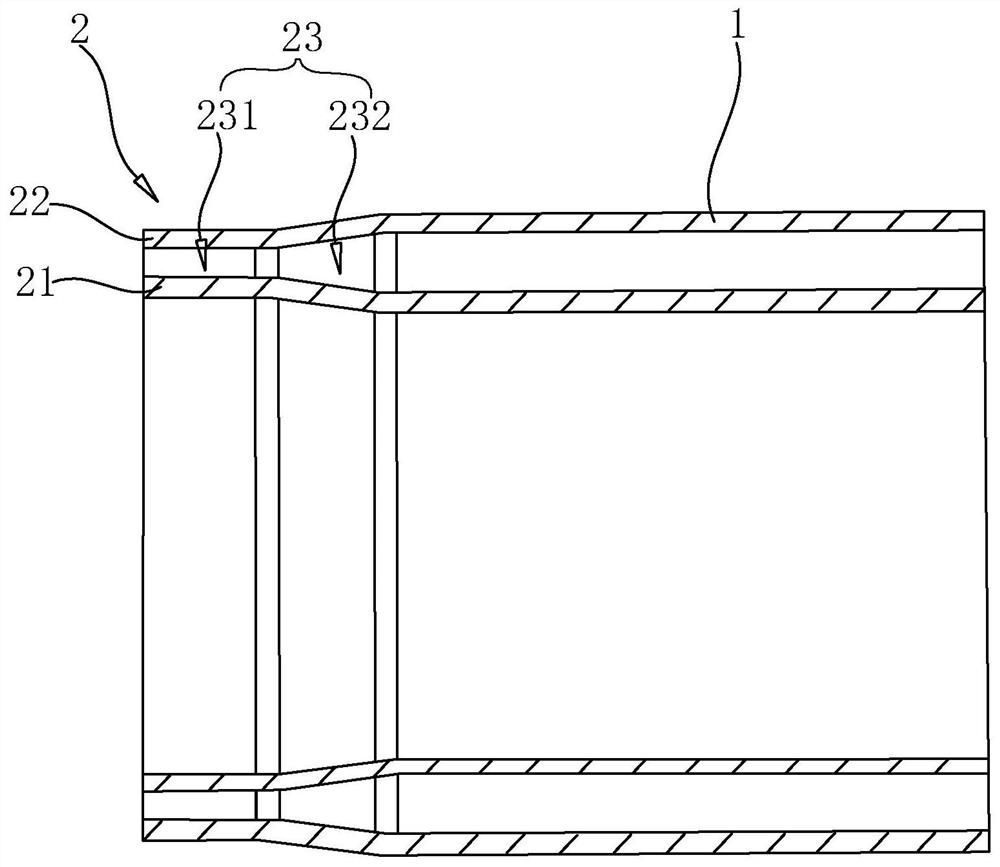
technical field [0001] The present application relates to the field of aero-engines, and in particular, to an anti-return air intake structure for a rotary detonation combustion chamber. Background technique [0002] The detonation combustion is realized by the leading fundamental wave compressing the explosive mixture to cause a high-speed chemical reaction; because the detonation combustion has the advantages of high heat release intensity per unit time, self-pressurization, high combustion efficiency, and low pollutant emissions, based on The propulsion technology of detonation combustion is an important development trend of future space technology. The rotary detonation combustion chamber is an annular combustion chamber that utilizes the detonation combustion method, and the fuel is jointly supplied by a plurality of nozzles in the head of the combustion chamber. [0003] like figure 1 As shown, in the related art, the rotary detonation combustion chamber intake struc...

Claims


Application Information

Patent Timeline
Patent Type & Authority Patents(China)
IPC IPC(8): F23R3/52F23R3/28
CPCF23R3/52F23R3/28F02C5/11F02K7/067F02K7/08F23R7/00F23R3/10F23D14/825F02C7/00
Inventor 宋飞龙吴云杨兴魁郭善广杨诏胥世达周剑平陈鑫
Owner AIR FORCE UNIV PLA
Learn More