Fire actuated release mechanism to separate electronic door lock from fire door

a release mechanism and electronic door lock technology, applied in the field of fire-rated electronic door locks, can solve the problems of difficult to meet this standard, many types of plastics will eventually begin to burn, and the relative low ignition temperature of these materials, so as to increase the pulling distance, increase the length of the sma wire, and maximize the distance of the sma material

Active Publication Date: 2014-10-30
SARGENT MANUFACTURING CO INC
View PDF8 Cites 25 Cited by
  • Summary
  • Abstract
  • Description
  • Claims
  • Application Information

AI Technical Summary

Benefits of technology

[0035]In the most highly preferred design, to maximize the distance that the SMA material pulls the electrical connector, the SMA wire is routed around multiple fixed points or studs. This allows an increase in the length of the SMA wire beyond the maximum dimension of the housing. The distance that the SMA can pull is a percentage of the total length of the SMA wire—typically about four percent. By increasing the length of the SMA wire, the pulling distance is increased, which ensures that the electrical connector will always be fully disconnected from the circuit board in the lock housing.
[0036]In another aspect of the invention, the SMA wire is located between a metal mounting plate and the fire door. This ensures that the SMA wire will be quickly heated to release the electrical connector before any significant deformation of the plastic housing or plastic mounts for the electrical circuit board occurs.
[0037]Because the connector is disconnected from pins attached to the circuit board, it is important that the pins and circuit board be firmly secured as the SMA wire begins to contract. If the mechanical mount or circuit board has begun to melt, the pulling force provided by the SMA material may cause the connector and pins to move together instead of causing the connector to be pulled off the pins. In yet another aspect of the invention, an insulating material is positioned between the circuit board and the heat source to prevent the circuit board or its mounts from melting or deforming before the SMA disconnection of the connector has been achieved.
[0038]In a further aspect of the invention, the SMA material is positioned adjacent to the fire door surface, as between the mounting plate and the fire door, so that heat transfer to the SMA material is maximized.

Problems solved by technology

A problem with the use of plastic for the housing and with plastic found in common off-the-shelf electronic components is the relatively low ignition temperature of these materials.
Many types of plastic will eventually begin to burn if they are exposed to sufficiently high temperatures.
It is very difficult to meet this standard when the lock components on the cold side are made of plastic.
The potential for undesirable ignition also limits the design and use of other components in electronic locks, such as common electronic components and mechanical components.
Even with a metal housing, the lock designer is often limited in the choice and positioning of components made of plastic.
Although limited amounts of plastic may be used inside the metal housing, it has not previously been possible to make the housing of plastic or to use significant amounts of plastic and other low ignition temperature materials.
If such materials are used for the lock housing on the “cold” side of a fire door, there is a significant risk that the heat of the fire will eventually melt and ignite such materials.
Ignition of lock components on the “cold” side during fire testing results in failure of the fire certification process.
For electronic locks, however, it is not sufficient merely to disconnect the mechanical lock mounting.
The term “low ignition temperature” as used herein refers to a sufficiently low ignition temperature that there is a significant risk of ignition when the material is exposed to heat on the cold side of a fire door during fire testing in which the heat from a fire is applied to the hot side of the fire door.

Method used


Image

  • Fire actuated release mechanism to separate electronic door lock from fire door
  • Fire actuated release mechanism to separate electronic door lock from fire door
  • Fire actuated release mechanism to separate electronic door lock from fire door

Examples


Embodiment Construction

)

[0050]In describing the preferred embodiment of the present invention, reference will be made herein to FIGS. 1-10 of the drawings in which like numerals refer to like features of the invention.

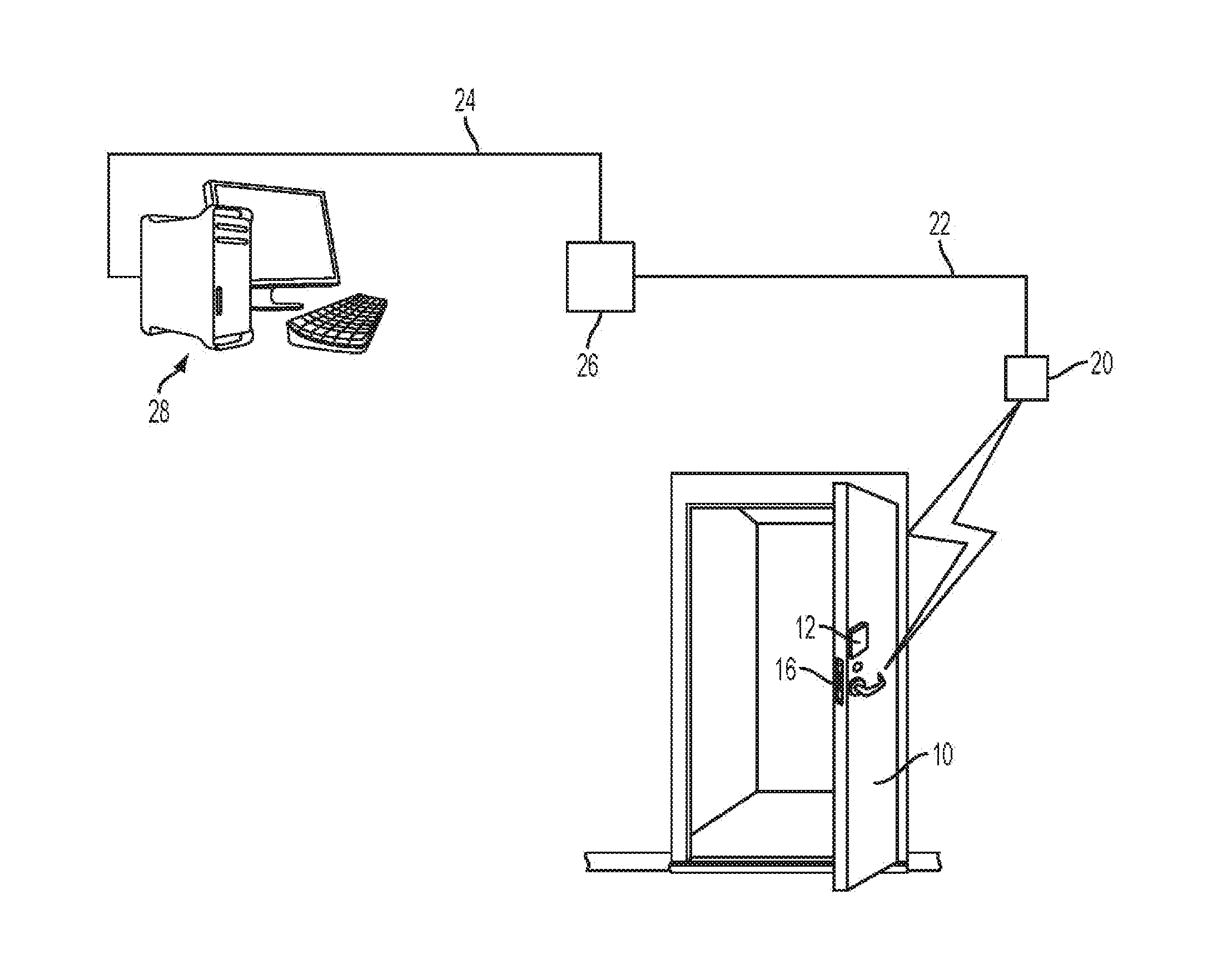
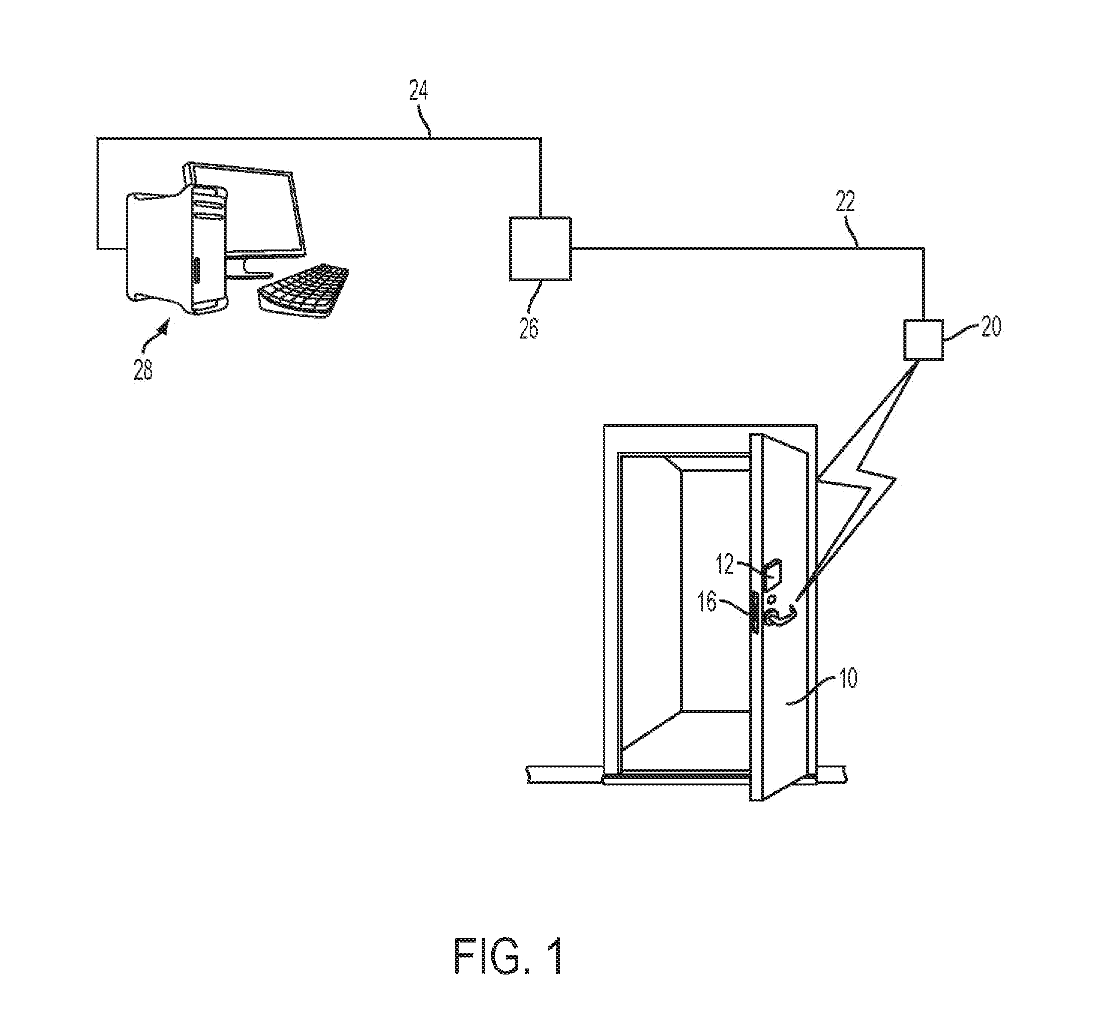
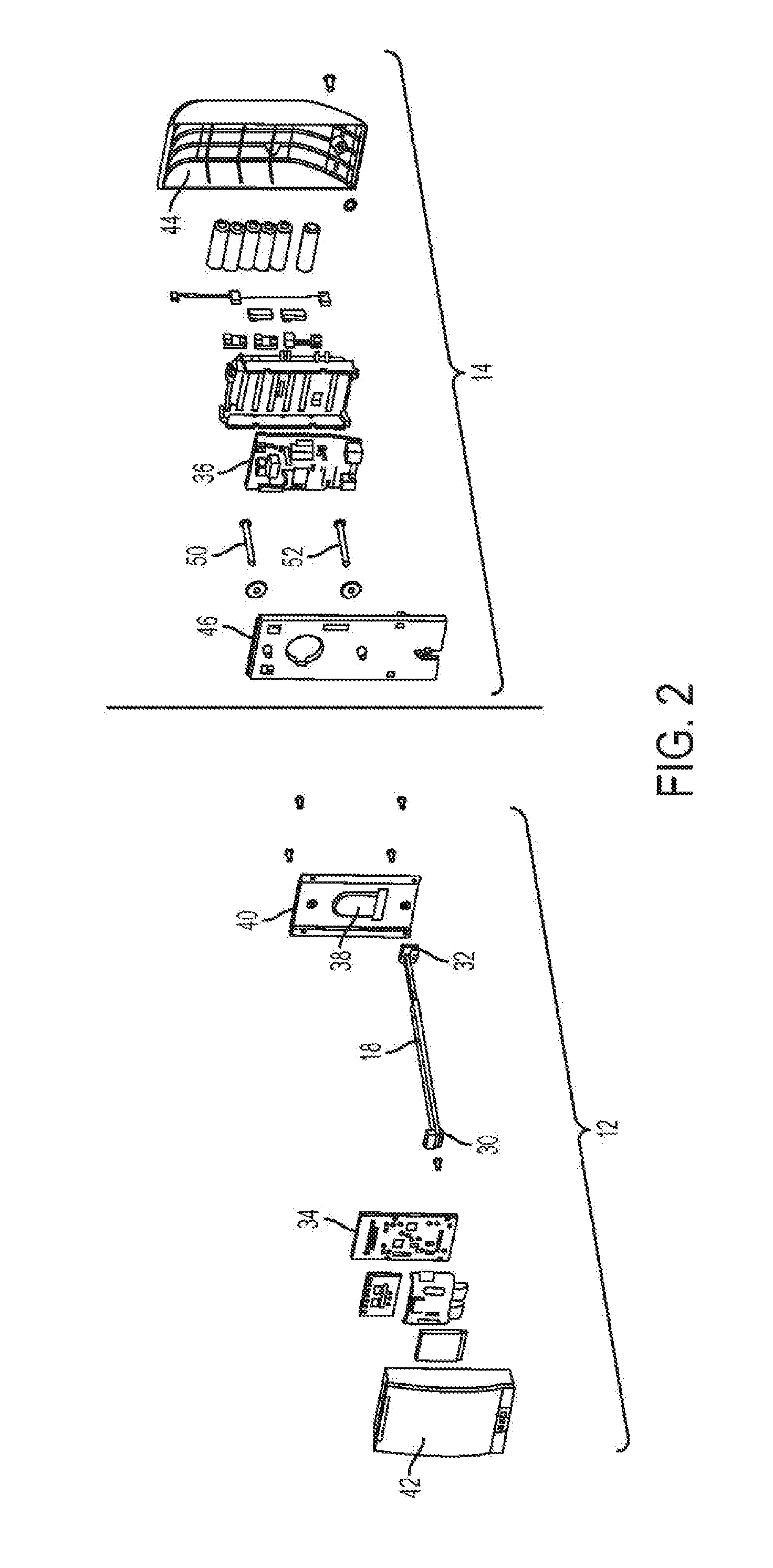
[0051]Referring to FIGS. 1 and 2, a fire door 10 has an electronic lock 12 mounted on a surface thereof. The lock portion 12 shown in FIG. 1 is electrically connected through the fire door 10 with electrical wires 18 to another portion of the lock 14 (see FIG. 2) located on the back side of the door.

[0052]The electronic lock 12, 14 functions to control mortise lock 16. The present invention will be illustrated in connection with a mortise lock design, however, the electronic lock may be used with bored locks, exit devices and other fire door hardware.

[0053]The electronic lock 12, 14 is wirelessly connected through wireless access point 20 and is then connected to computer 28 through wires 22 and 24 and other network circuitry 26, which may be hubs, switches, routers or the like, or other cus...


PUM


Abstract

A release mechanism is actuated by the heat of a fire to electrically and mechanically disconnect electrical wiring from an electronic lock having a plastic housing. The electronic lock is mounted on a fire door and as it is heated by a fire on the opposite side of the fire door, mounts that hold the lock melt, releasing the electronic lock to drop away from the fire door and prevent ignition of the plastic housing. The release mechanism may use shape memory alloy wire to contract and disconnect a ribbon cable. Solder connectors may also be used to disconnect wires. Intumescent material that expands when heated is used to drive the lock mechanism away from the fire door and insulation is used to control the timing of melting.

Description

BACKGROUND OF THE INVENTION[0001]1. Field of the Invention[0002]The present invention relates to fire rated electronic door locks that have components made of plastic or other materials having a relatively low ignition temperature. More specifically, the present invention relates to a fire rated electronic door lock that includes a mechanism, actuated by the heat of a fire on the hot side of a fire door, which acts to disconnect wiring from lock components mounted on the cold side of the fire door. By disconnecting wiring from the cold side, the cold side lock components are no longer tethered with wiring to the fire door and can drop away to prevent ignition and improve fire resistance.[0003]2. Description of Related Art[0004]Electronic door locks typically include lock components mounted in housings on opposite sides of the door. These lock components may include card readers, proximity detectors, keypads, LED and LCD displays and indicators, batteries, printed circuit board assem...

Claims


Application Information

Patent Timeline
Patent Type & Authority Applications(United States)
IPC IPC(8): E05B65/10A62C2/24
CPCA62C2/242E05B65/104E05B65/108E05B2015/1664E05B17/0075Y10T70/8946
Inventor ELLIS, DAVID D.LOWDER, SCOTT B.LEITES, RICKLORELLO, MICHAEL J.
Owner SARGENT MANUFACTURING CO INC
Why Eureka
Try Eureka