Liquid separator and compressor

A liquid distributor and flow guide technology, applied in the field of compressors, can solve the problems of reducing the liquid separation efficiency of the filter screen and increasing the liquid shock

Active Publication Date: 2021-12-21
GREE ELECTRIC APPLIANCES INC
View PDF4 Cites 1 Cited by
  • Summary
  • Abstract
  • Description
  • Claims
  • Application Information

AI Technical Summary

Problems solved by technology

[0004] Based on this, when the traditional liquid separator is in use, when a large amount of liquid returns, it directly impacts the filter in the liquid separator, reducing the liquid separation efficiency of the filter, causing the refrigerant entering the compressor pump body to be mixed with liquid, thereby increasing the In order to solve the problem of the probability of liquid shock, a liquid separator and compressor are proposed. When the liquid separator and compressor are in use, they can prevent the heat exchange medium to be separated from directly impacting the filter element, thereby improving the filtering effect of the filter element. , which can reduce the probability of compressor liquid shock

Method used


Image

  • Liquid separator and compressor
  • Liquid separator and compressor
  • Liquid separator and compressor

Examples


Embodiment Construction

[0035] In order to make the above objects, features and advantages of the present invention more comprehensible, specific implementations of the present invention will be described in detail below in conjunction with the accompanying drawings. In the following description, numerous specific details are set forth in order to provide a thorough understanding of the present invention. However, the present invention can be implemented in many other ways different from those described here, and those skilled in the art can make similar improvements without departing from the connotation of the present invention, so the present invention is not limited by the specific embodiments disclosed below.

[0036] In describing the present invention, it should be understood that the terms "center", "longitudinal", "transverse", "length", "width", "thickness", "upper", "lower", "front", " Back", "Left", "Right", "Vertical", "Horizontal", "Top", "Bottom", "Inner", "Outer", "Clockwise", "Counte...


PUM


Abstract

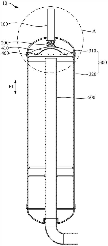
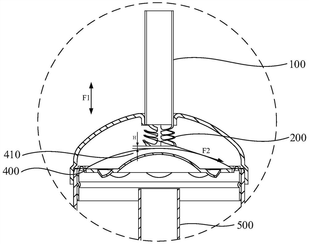
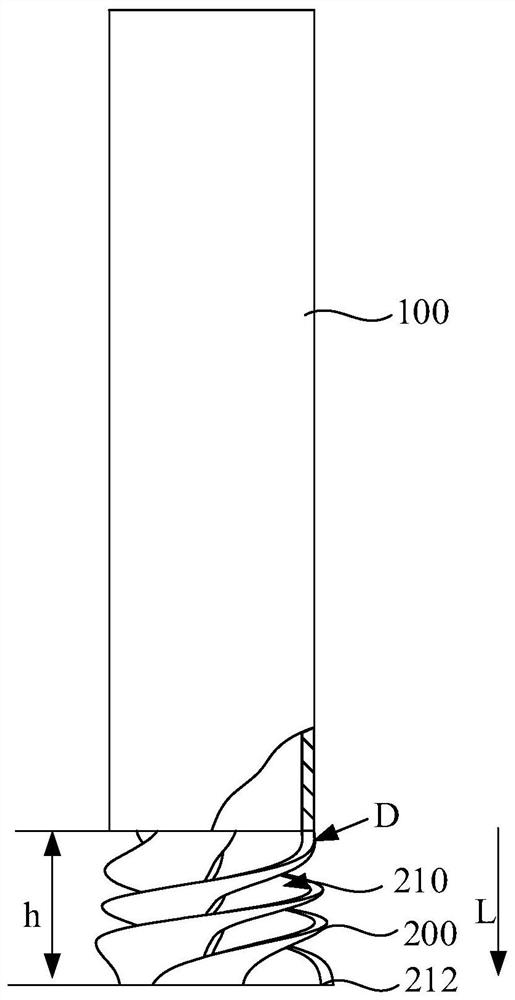
The invention discloses a liquid separator and a compressor. The liquid separator comprises an air inlet pipe, a flow guide piece, a barrel and a filtering piece, wherein the air inlet pipe is used for connecting and guiding a to-be-separated heat exchange medium; the flow guide piece is connected to the air inlet pipe, a flow guide channel spirally extending in an axial direction of the air inlet pipe is formed in the flow guide piece, and the inlet end of the flow guide channel communicates with an outlet of the air inlet pipe; and the filtering piece is arranged in the barrel, the flow guide piece extends into the barrel, the flow guide piece and the filtering piece are arranged at intervals in an axial direction of the barrel, the filtering piece is used for filtering the to-be-separated heat exchange medium discharged to the filtering piece along the outlet end of the flow guide channel, and a discharge direction of the outlet end of the flow guide channel is not perpendicular to the filtering surface of the filtering piece. When the liquid separator and the compressor are used, the to-be-separated heat exchange medium can be prevented from directly impacting the filtering piece, so that the filtering effect of the filtering piece is improved, and the liquid impact probability of the compressor can be reduced.

Description

technical field [0001] The invention relates to the technical field of compressors, in particular to a liquid separator and a compressor. Background technique [0002] After the refrigeration compressor is left standing at low temperature, a large amount of refrigerant is accumulated in the compressor due to the migration of the refrigerant. When the compressor is started, it is easy to cause the oil level of the compressor to drop rapidly, or even lack of oil. When the compressor runs for a period of time, a large amount of oil or refrigerant liquid will flow into the suction port. Therefore, compressors are generally equipped with corresponding liquid separators for refrigeration oil and refrigerant. The liquid separator generally includes an air inlet pipe and a filter screen, and the filter screen is used to separate the refrigerant and refrigerating oil entering along the air inlet pipe. [0003] When the traditional liquid separator is in use, when a large amount of...

Claims


Application Information

Patent Timeline
Patent Type & Authority Applications(China)
IPC IPC(8): F25B43/00F25B43/02F25B31/00
CPCF25B43/003F25B43/02F25B31/00F25B2500/28
Inventor 岳震周丹吕丹丹李成龙苏达荣王大号
Owner GREE ELECTRIC APPLIANCES INC
Why Eureka
Try Eureka