
Cable butt joint device

A docking device and cable technology, which is applied in the direction of instruments, optics, light guides, etc., can solve the problems of low efficiency, unsuitable docking device for optical cable docking, and high cost, so as to achieve high docking efficiency, improve on-site docking efficiency, and high docking accuracy Effect

Pending Publication Date: 2021-12-21
HANGZHOU FUTONG COMM TECH CO LTD
View PDF6 Cites 0 Cited by
  • Summary
  • Abstract
  • Description
  • Claims
  • Application Information

AI Technical Summary

Problems solved by technology

[0005] In order to solve the problems that the existing docking device is not suitable for optical cable docking, and the traditional welding method has low efficiency and high cost, the present invention provides a cable docking device

Method used


Image

  • Cable butt joint device
  • Cable butt joint device
  • Cable butt joint device

Examples


Embodiment

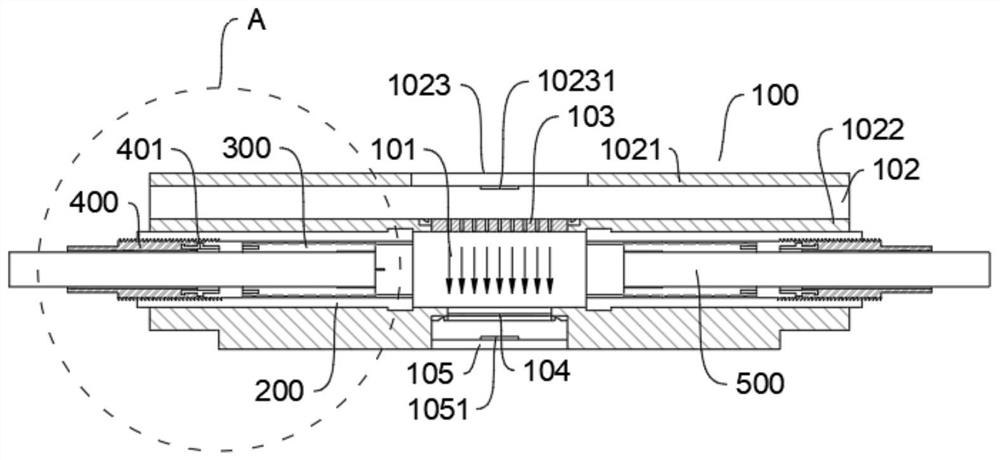
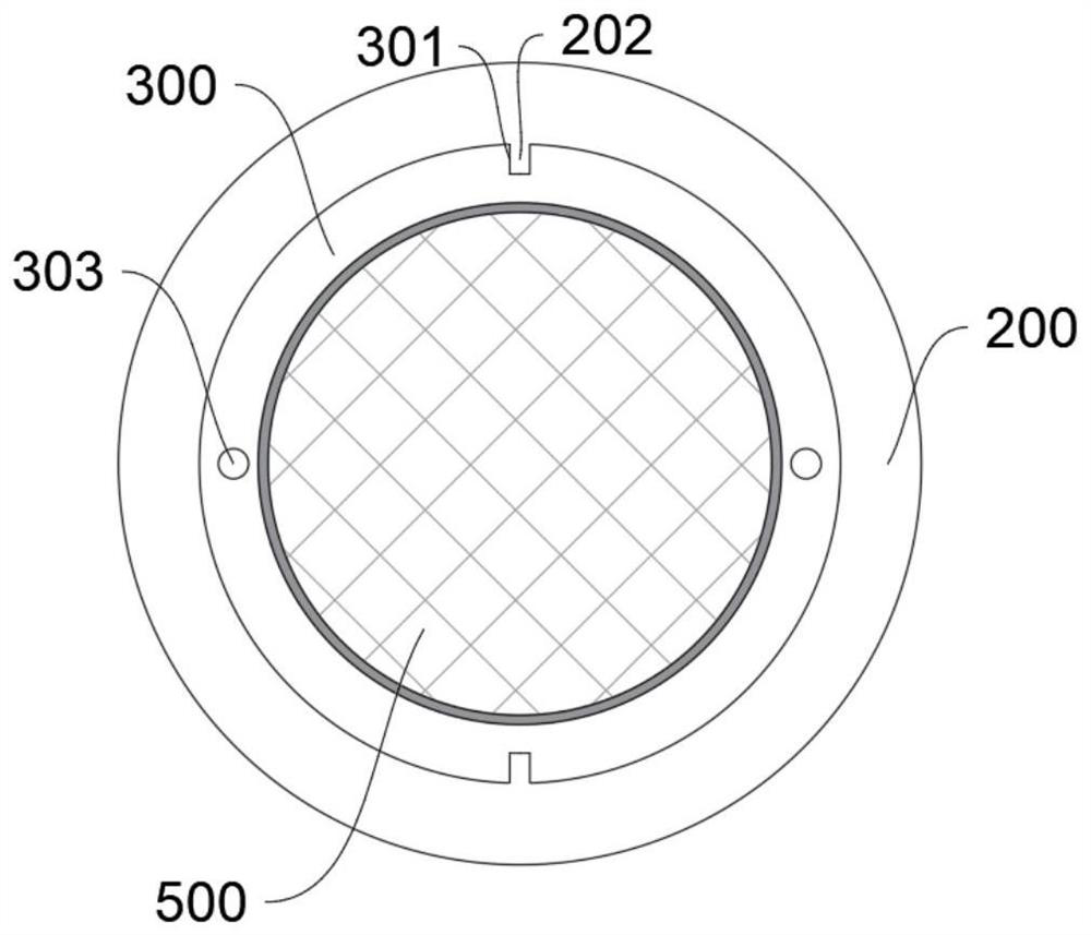
[0058] a kind of like figure 1 The cable docking device shown, this device can be applied to the docking of cables and optical cables. This embodiment only uses optical cables as an example to illustrate, but the two are substantially similar, and the protection content should not be limited due to the content of the embodiment;

[0059] The on-site cable docking device specifically includes:

[0060] A main body 100, the main body 100 is provided with an accommodating channel 101 for accommodating, docking and fixing the optical cable 500, and a light source channel 102 parallel to the accommodating channel 101;

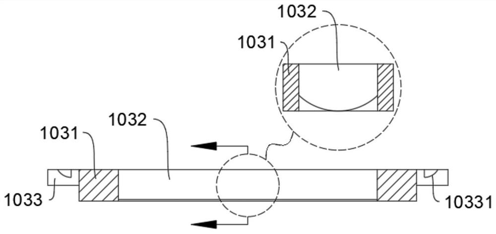
[0061] Both ends of the accommodation channel 101 are open, and the inner wall 1022 of the light source channel 102 corresponding to the middle part of the accommodation channel 101 is provided with a through groove connecting the light source channel 102 and the accommodation channel 101, and a light guide 103 is arranged in the through groove;

[0062]Two main fi...


PUM


Abstract

The invention belongs to cable equipment, and particularly relates to a cable butt joint device. The device comprises a main body which is provided with a containing channel and a light source channel which are parallel to each other; a through groove is formed in the portion, corresponding to the middle of the containing channel, of the inner wall of the light source channel, and a light guide piece is arranged in the through groove. an observation mirror is correspondingly arranged on the side wall of the opposite side of the containing channel; two main fixing pieces are symmetrically arranged at the two ends in the containing channel, sliding channels parallel to the containing channel are formed in the main fixing pieces, the sliding channels of the two main fixing pieces are symmetrical and aligned with each other, and a sliding cylinder used for wrapping the outer side of an optical cable and capable of driving the optical cable to move is arranged in the sliding channel of each main fixing piece; the inner wall of each sliding channel is connected with the corresponding sliding cylinder in a matched mode, so that the sliding cylinder can move in the corresponding sliding channel along a sliding rail, and the sliding rail is parallel to the containing channel. The cable butt joint device can be effectively suitable for butt joint of single-core optical cables, particularly suitable for butt joint of butterfly-shaped single-core optical cables and suitable for butt joint of cables at the same time, and has general applicability.

Description

technical field [0001] The invention belongs to the field of cable equipment, in particular to a cable docking device. Background technique [0002] Both fiber optic and electrical cables are an important part of the telecommunications network that makes up our everyday lives. To form a telecommunications network group, a large number of optical cables and cables are required for connection. [0003] At present, the traditional optical cable connection cannot be connected as simply as a wire, and a fusion splicer is required to perform hot-melt connection on the bare optical fiber. Not only need to invest in expensive equipment, but also need to be proficient in fusion splicing technology, so it is difficult to popularize it on a large scale. In an optical fiber transmission node or equipment, it is often necessary to splice dozens to hundreds of core optical fibers at the same time. Due to the large size of the fusion splicer and the need for power , It is difficult to us...

Claims


Application Information

Patent Timeline
Patent Type & Authority Applications(China)
IPC IPC(8): G02B6/38
CPCG02B6/385G02B6/3833
Inventor 孙林波陆健红
Owner HANGZHOU FUTONG COMM TECH CO LTD
Learn More