
Fabricated integrated house steel bar truss floor support plate and assembling method

A steel truss and integrated building technology, which is applied to floors, buildings, building reinforcements, etc., can solve problems such as large deformation and difficult welding and assembly operations

Active Publication Date: 2021-12-24
浙江钢本集成房屋有限公司
View PDF8 Cites 1 Cited by
  • Summary
  • Abstract
  • Description
  • Claims
  • Application Information

AI Technical Summary

Problems solved by technology

[0003] Since the overall length of the upper chord steel bar 1 and the lower chord steel bar 3 is relatively long, the positions of the web steel bar 2, the upper chord steel bar 1, and the lower chord steel bar 3 need to be relatively initially fixed during the welding process, but because the upper chord steel bar 1 itself is longer And it will involve connecting two web steel bars 2 at the same time. Even if the two ends of the upper string steel bar 1 are properly positioned, the closer the upper string steel bar 1 is to the middle, the greater its deformation will be, and the welding and assembly operation will be difficult.

Method used


Image

  • Fabricated integrated house steel bar truss floor support plate and assembling method
  • Fabricated integrated house steel bar truss floor support plate and assembling method
  • Fabricated integrated house steel bar truss floor support plate and assembling method

Examples


Embodiment 1

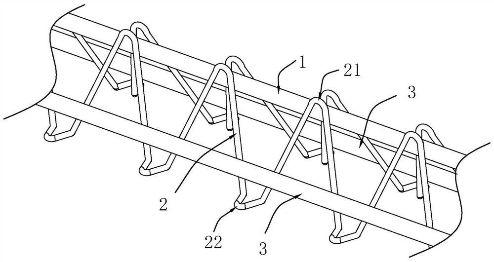
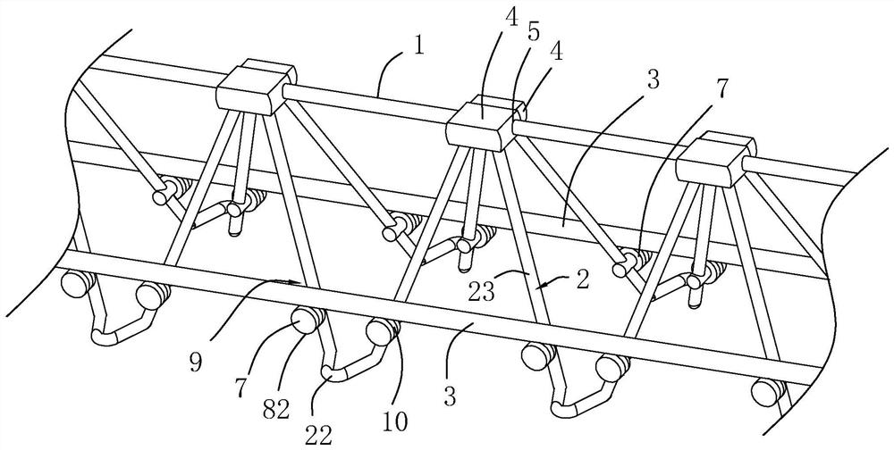
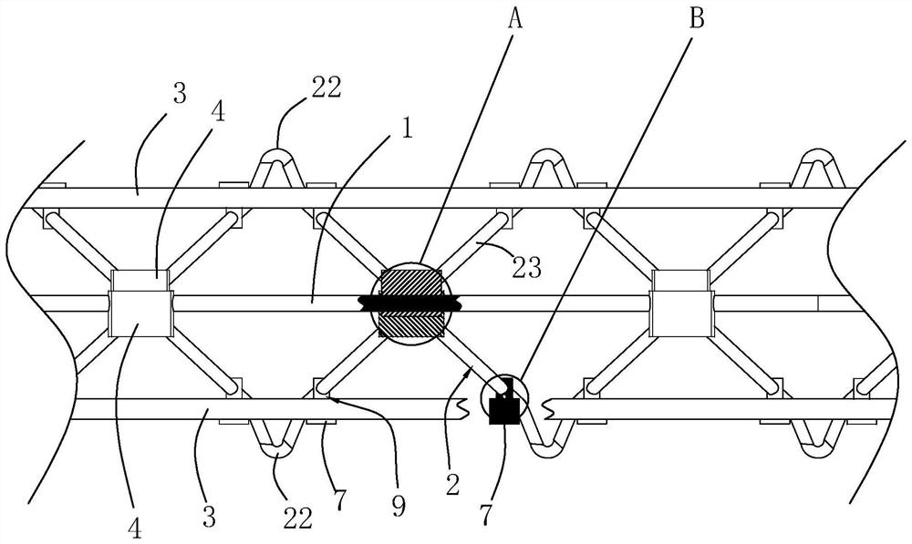
[0047] A prefabricated integrated house reinforced truss floor deck, see figure 2 , including upper chord reinforcement 1, two web reinforcement bars 2, and two lower chord reinforcement bars 3, the shape of upper chord reinforcement 1 and lower chord reinforcement 3 are elongated, and upper chord reinforcement 1 and two lower chord reinforcement 3 are distributed in triangular points.

[0048] see figure 2 , the two web bars 2 and the two lower chord bars 3 are respectively located on both sides of the upper chord bar 1 . Each web steel bar 2 is bent into a wave shape, and there are multiple crests and troughs in the web steel bar 2. The folding position is the lower connection end 22 .

[0049] see figure 2 as well as image 3 , the upper connecting end 21 of each web steel bar 2 is equipped with an upper connecting sleeve 4, and the upper connecting sleeve 4 is provided with an upper through groove 5, and the upper connecting sleeves 4 on the two web steel bars 2 are...

Embodiment 2

[0055] Embodiment 2: On the basis of Embodiment 1, the following structure is added.

[0056] see Figure 6 , also includes the adjustment rod 11, the two ends of the adjustment rod 11 are provided with threaded sections and the two threaded sections have opposite directions of rotation, the middle sleeve support 8 is provided with threaded holes 12, and the threaded sections at both ends of the adjustment rod 11 are respectively threaded to the corresponding Adjacent to the threaded holes 12 of the two middle sleeve supports 8 .

Embodiment 3

[0057] Embodiment 3: On the basis of Embodiment 1 or Embodiment 2, the following structure is added.

[0058] see Figure 7 , the support end 82 of the middle sleeve support 8 is provided with a rotating piece 13 for rotation, and the rotation axis of the rotation piece 13 is eccentric to the rotation axis of the middle sleeve support 8 .

[0059] The cross-section of the rotating piece 13 is consistent with the cross-section of the middle sleeve support 8 .

[0060] When the rotating piece 13 rotates to the position of the end face of the middle sleeve support 8, the rotating piece 13 can completely cover the end position of the middle sleeve support 8, and the overall structure is compact; , the end of the rotating piece 13 protrudes from the position above the middle cover support 8, and the rotating piece 13, the middle cover support 8, and the middle connecting section 23 form a placement space 9.


PUM


Abstract

The invention provides a fabricated integrated house steel bar truss floor support plate and an assembly method. The fabricated integrated house steel bar truss floor support plate comprises an upper chord reinforcing steel bar, two web member reinforcing steel bars and two lower chord reinforcing steel bars, the two web member reinforcing steel bars and the two lower chord reinforcing steel bars are located on the two sides of the upper chord reinforcing steel bar respectively, each web member reinforcing steel bar is bent into a wave shape, the wave crest bending position of each web member reinforcing steel bar is an upper connecting end, the wave trough bending position of each web member reinforcing steel bar is a lower connecting end, upper connecting sleeves are arranged at the upper connecting ends of the web member steel bars, upper penetrating grooves are formed in the upper connecting sleeves, the upper connecting sleeves on the two web member steel bars are connected in an inserted mode, upper penetrating grooves in the two upper connecting sleeves which are connected in an inserted mode are communicated, and the upper chord steel bars penetrate through the upper penetrating grooves in all the upper connecting sleeves at the same time. The fabricated integrated house steel bar truss floor support plate is high in structural stability and low in welding and assembling operation difficulty, the project progress is accelerated, the bottom is flat, and the decoration cost is reduced.

Description

technical field [0001] The invention relates to a prefabricated building structure, in particular to a prefabricated integrated building steel bar truss floor deck and an assembling method. Background technique [0002] The traditional reinforced truss floor deck structure is as attached figure 1 As shown, it includes an upper chord reinforcement 1 and two lower chord reinforcements 3. The upper chord reinforcement 1 and the lower chord reinforcement 3 are distributed in a triangular position, and a web reinforcement 2 is arranged between the upper chord reinforcement 1 and the lower chord reinforcement 3. The web The steel bar 2 is bent into a wave shape, the crest bending position of the web steel bar 2 is the upper connection end 21, the wave trough bending position of the web steel bar 2 is the lower connection end 22, and the upper connection end 21 is welded to the upper chord steel bar 1, The lower connecting end 22 is welded to the upper chord steel bar 1 . [0003...

Claims


Application Information

Patent Timeline
IPC IPC(8): E04B5/00E04C5/06
CPCE04B5/00E04C5/0627
Inventor 郑正兵
Owner 浙江钢本集成房屋有限公司
Learn More