Wafer automatic bearing system and method for conveying wafer by adopting wafer automatic bearing system

A carrier system and wafer carrier technology, which is applied in the manufacture of conveyor objects, electrical components, semiconductor/solid-state devices, etc., which can solve the problems of unreproducible wafer deposition repeatability, inaccurate determination of wafer position, and wafer film deposition quality. It can improve the position accuracy and transfer crystallinity, reduce the movement steps, and improve the product qualification rate.

Pending Publication Date: 2021-12-24
PIOTECH CO LTD
View PDF0 Cites 0 Cited by
  • Summary
  • Abstract
  • Description
  • Claims
  • Application Information

AI Technical Summary

Problems solved by technology

[0003] In the prior art, wafer carrying devices for carrying and transferring wafers generally have some disadvantages. For example, some carrying devices cause the wafer to experience more movement processes during the transfer process, so the position error of the wafer is relatively large. Large, and even an alarm occurs during the transfer process; another example, the final position of the wafer on the heating plate cannot be accurately determined, resulting in poor quality of wafer film deposition; in addition, it may also lead to unreliable repeatability of wafer deposition copy

Method used


Image

  • Wafer automatic bearing system and method for conveying wafer by adopting wafer automatic bearing system
  • Wafer automatic bearing system and method for conveying wafer by adopting wafer automatic bearing system
  • Wafer automatic bearing system and method for conveying wafer by adopting wafer automatic bearing system

Examples


Embodiment Construction

[0049] Embodiments of the present application will be described in detail below in conjunction with the accompanying drawings. Aspects of the present application may be understood more readily by reading the following description of specific embodiments with reference to the accompanying drawings. It should be noted that these embodiments are only exemplary, which are only used to explain and illustrate the technical solutions of the present application, rather than limiting the present application. Those skilled in the art can make various modifications and transformations on the basis of these embodiments, and all technical solutions obtained through equivalent transformations belong to the protection scope of the present application. The names of various components used in this manual are for the purpose of illustration only and do not have a limiting effect. Different manufacturers may use different names to refer to components with the same function.

[0050] see figure...


PUM


Abstract

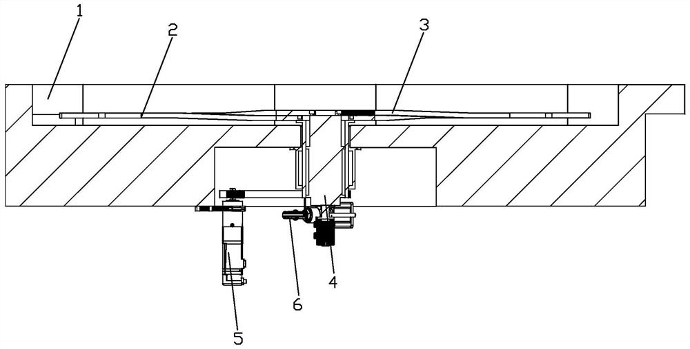
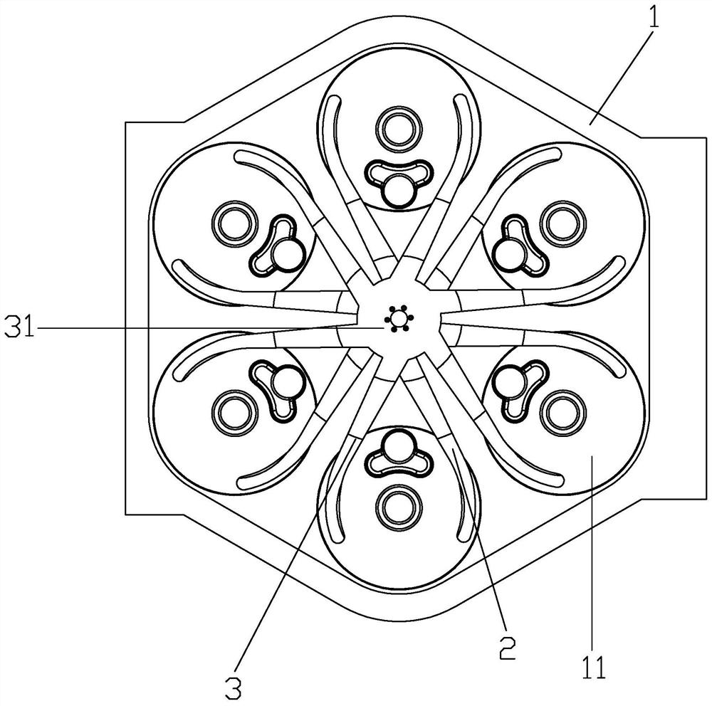
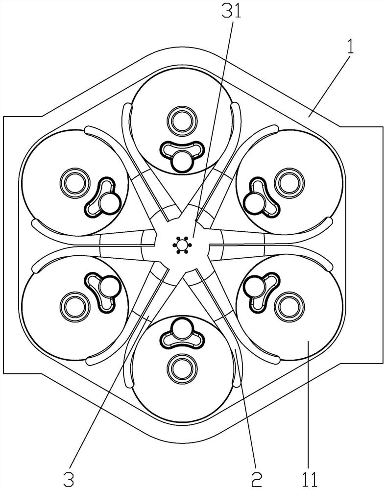
The invention discloses an automatic wafer bearing system and a method for conveying wafers by adopting the wafer automatic bearing system. The system comprises a vacuum chamber which is provided with a plurality of wafer bearing stations; multiple first paddles and multiple second paddles which are located in the vacuum chamber and can synchronously rotate respectively, wherein each second paddle and the corresponding first paddle form a pair of paddles so as to jointly bear a wafer; double sets of magnetic fluids which are in sealed connection with the vacuum chamber and are connected to the plurality of first paddles and the plurality of second paddles so as to drive one or both of the first paddles and the second paddles to rotate; a first driving mechanism which is connected to the double sets of magnetic fluid so as to drive the multiple first paddles and the multiple second paddles to synchronously rotate in the same direction through the double sets of magnetic fluid; and a second driving mechanism which is also connected to the double sets of magnetic fluid so as to realize relative rotation between the plurality of first paddles and the plurality of second paddles through the double sets of magnetic fluid. The system can reduce the movement steps of the wafer in the conveying process, so that the conveying precision and stability of the wafer are improved, and the position error of the wafer is reduced.

Description

technical field [0001] The invention relates to the field of semiconductor wafer processing, in particular to a system and method for carrying and transferring wafers in a semiconductor processing chamber. Background technique [0002] Wafers are the substrates used to fabricate semiconductor devices. In order to prepare semiconductor devices (such as integrated circuits, semiconductor light-emitting devices, etc.), it is necessary to place the wafer in a semiconductor processing chamber for heating and deposition processing (such as chemical vapor deposition (CVD) and plasma enhanced chemical vapor deposition (PECVD), etc.) . In this process, multiple wafers need to be sequentially placed on different stations (heating plates). Therefore, a special wafer carrying device is needed to place the wafers one by one on the heating plate and transfer them to different work stations. [0003] In the prior art, wafer carrying devices for carrying and transferring wafers generally...

Claims


Application Information

Patent Timeline
Patent Type & Authority Applications(China)
IPC IPC(8): H01L21/677H01L21/687
CPCH01L21/67739H01L21/687H01L21/68707H01L21/68764H01L21/68771H01L21/6719H01L21/67742H01L21/68792H01L21/67709H01L21/6838
Inventor 杨华龙杨德赞刘闻敏吴凤丽
Owner PIOTECH CO LTD
Why Eureka
Try Eureka