Fluid circulation pump

A fluid and fluid flow technology, applied in the direction of pumps, parts of pumping devices for elastic fluids, pump components, etc., can solve problems such as head loss of check valves, and achieve the effect of improving capacity and efficiency

Active Publication Date: 2021-12-28
AMS R & D
View PDF4 Cites 0 Cited by
  • Summary
  • Abstract
  • Description
  • Claims
  • Application Information

AI Technical Summary

Problems solved by technology

[0005] This check valve is a component that is subject to wear and causes loss of head pressure

Method used


Image

  • Fluid circulation pump
  • Fluid circulation pump
  • Fluid circulation pump

Examples


Embodiment Construction

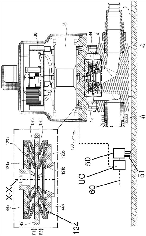
[0032] As described above, the pump 100 of the present invention includes the suction inlet 41 and the discharge outlet 42 .

[0033] The pump includes a motor 46 which can be Figure 1a located outside chamber 44 as shown, or as Figure 2 to Figure 4 Shown inside chamber.

[0034] In all embodiments, this motor 46 is mechanically connected to the movable part in order to be able to move it inside the chamber 44 .

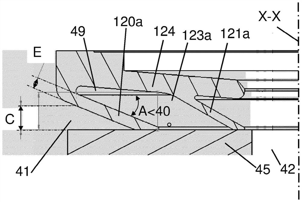
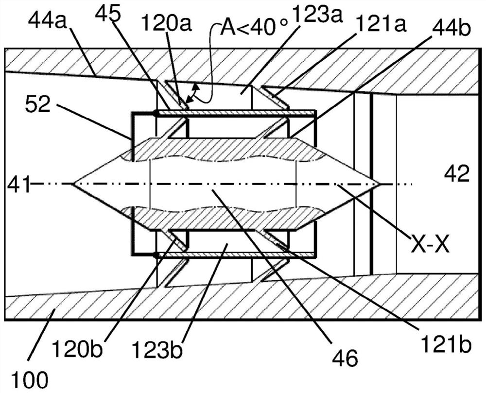
[0035] The pump 100 also has a first upstream lip 120a placed closer to the suction inlet 41 than the discharge outlet 42 and a first downstream lip 121a placed closer to the discharge outlet 121a. outlet 42 instead of suction inlet 41.

[0036] These first upstream and downstream lips 120a, 121a are placed between one of the sides of the movable member 45 and the first wall 44a of the chamber 44 so that between these first upstream and downstream lips 120a, 121a A first space 123a is defined.

[0037] The arrangement of the lip defining the first passage 123a ...


PUM


Abstract

Fluid circulation pump (100) comprising a suction inlet (41), a delivery outlet (42) and a movable part (45) that can move in the chamber (44). The pump (100) comprises first upstream (120a) and downstream (121a) circular lips such that: over a first portion (P1) of the movement of said movable part (45) in the chamber (44), the first upstream circular lip (120a) then allows a free flow of fluid between the first space (123a) and the suction inlet (41); and that over a second portion (P2) of said movement, the first upstream circular lip (120a) provides sealing that prevents the flow of fluid towards the suction inlet (41), the first downstream circular lip (121a) allowing the flow of fluid from the first space (123a) towards said delivery outlet (42) and preventing the flow of fluid towards said first space (123a).

Description

technical field [0001] The present invention relates to the field of fluid flow pumps. Background technique [0002] Known pumps are provided with a chamber whose volume varies according to the movement of parts movable inside the chamber, which chamber is equipped with a non-return valve upstream of the chamber and downstream of the chamber with a check valve. [0003] When the volume of the chamber increases, then the chamber is under suction, so the upstream check valve is opened and the downstream check valve is closed, and fluid is then drawn into the chamber. [0004] When the volume of the chamber is reduced, then the chamber is under compression, so the upstream check valve is closed and the downstream check valve is opened, and fluid is then discharged from the chamber to the discharge outlet. [0005] Such check valves are components that are subject to wear and cause head loss. Contents of the invention [0006] It is an object of the present invention to pro...

Claims


Application Information

Patent Timeline
Patent Type & Authority Applications(China)
IPC IPC(8): F04B19/20F04B43/00F04B43/02F04B43/08F04B43/09F04B53/10
CPCF04B43/084F04B43/09F04B43/028F04B43/0054F04B53/1047F04B19/20
Inventor G·德莱斯E·吉列明
Owner AMS R & D
Why Eureka
Try Eureka