Control mechanism and brake device

A control mechanism and control terminal technology, applied in the direction of brake transmission, control valve, air release valve, brake, etc., can solve the problems that the brake does not have anti-skid function, the anti-skid device does not have braking function, etc.

Pending Publication Date: 2022-01-07
ZHEJIANG RUILI AIR COMPRESSOR EQUIP CO LTD
View PDF1 Cites 0 Cited by
  • Summary
  • Abstract
  • Description
  • Claims
  • Application Information

AI Technical Summary

Problems solved by technology

[0005] However, in the above-mentioned prior art, the brake and the anti-skid device work independently, that is, the brake can only provide braking force to the wheels, and the anti-skid device can only adjust the braking force of the brake. The brake itself does not have an anti-skid function, and the anti-skid device itself Without braking function

Method used


Image

  • Control mechanism and brake device

Examples


Embodiment 1

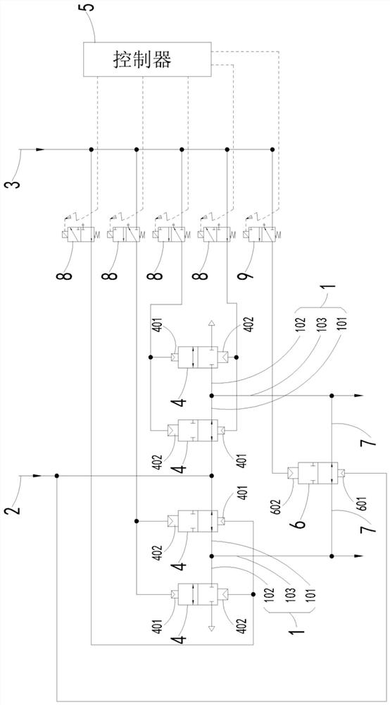
[0033] In this embodiment, a control mechanism is provided, including a three-way pipeline 1 and a first air source interface 2;

[0034] The three-way pipeline 1 is composed of a first pipeline 101, a second pipeline 102 and a third pipeline 103 in a three-way shape, and the first pipeline 101 and the second pipeline 102 are respectively connected to the valve chambers of a pair of control valves 4 One, the control end of any control valve 4 is at least controlled by the same controller 5 respectively;

[0035] The two control valves 4 connected to the same three-way pipeline 1 are restricted to alternative conduction by the controller 5 , and the valve chamber of one of the control valves 4 is connected to the first interface 2 of the gas source through the pipeline.

[0036] For ease of understanding, a pair of control valves 4 will be described in the form of the first control valve 4 and the second control valve 4;

[0037] Those skilled in the art should understand that...

Embodiment 2

[0088] In this embodiment, a control mechanism is provided; the control mechanism of this embodiment has the following differences from the control mechanism in the aforementioned embodiment 1:

[0089] The control valve 4 and the second control valve 6 are respectively provided as solenoid valves.

[0090] Adopt electromagnetic valve as control valve 4 and second control valve 6, can realize the braking function and anti-slip function to braking mechanism (clamp) equally; With respect to aforementioned embodiment 1, the control mechanism in this embodiment saves The number of solenoid valves used to control the pneumatic valve and the second pneumatic valve is actually less.

[0091] The rest of the structure of the control mechanism in this embodiment is the same as that of the aforementioned embodiment 1 except for the control valve 4 and the second control valve 6 , and will not be repeated here.

Embodiment 3

[0093] In this embodiment, a control mechanism is provided; the control mechanism of this embodiment has the following differences from the control mechanism in the aforementioned embodiment 1:

[0094] The control valve 4 is set as a solenoid valve, and the second control valve 6 is set as a pneumatic valve;

[0095] The electromagnetic valve 8 is adopted as the control valve 4, and the second control valve 6 is set as a pneumatic valve, which can also realize the braking function and anti-skid function for the braking mechanism (clamp); with respect to the foregoing embodiment 1, the present embodiment The control mechanism in the utility model saves the number of solenoid valves used to control the pneumatic valve, and the actual number of valves used is less.

[0096] The rest of the structure of the control mechanism in this embodiment is the same as that of the aforementioned embodiment 1 except for the control valve 4 , and will not be repeated here.


PUM


Abstract

The invention relates to the field of brakes for rail transit, in particular to a control mechanism and a brake device. The control mechanism is characterized by comprising a three-way pipeline and a first connector of an air source; the three-way pipeline is in a three-way shape formed by a first pipeline, a second pipeline and a third pipeline, the first pipeline and the second pipeline are respectively connected with one of valve cavities of a pair of control valves, and the control end of any control valve is at least respectively controlled by the same controller; through the control mechanism composed of the controller, the two control valves and the three-way pipeline, on one hand, compressed air can be injected into the braking mechanism, on the other hand, the compressed air in the braking mechanism can be emptied, and the control mechanism has the braking function of the control mechanism in the prior art and also has the anti-skid function in the prior art.

Description

technical field [0001] The invention relates to the field of rail transit brakes, in particular to a control mechanism and a braking device. Background technique [0002] The bogies of rail transit (such as: high-speed rail, bullet train, train, subway, light rail, etc.) usually include one axle and two axles, and the two ends of the first axle and the second axle are respectively provided with wheels, so that the carriages of rail transit pass through the bogie. Wheels run on rails. [0003] During the operation of the rail transit, the rail transit has motion states such as static, acceleration, running, and deceleration. When the rail transit changes to a deceleration state, the wheels are affected by the brakes, and the speed of the wheels changes from a state greater than zero to Zero, at this time, the carriages of rail transit continue to move forward under the action of inertia, while the wheels are in a sliding state relative to the rails, which makes the carriages...

Claims


Application Information

Patent Timeline
Patent Type & Authority Applications(China)
IPC IPC(8): B60T13/36B60T15/02B61H11/06
CPCB60T13/36B60T15/027B61H11/06
Inventor 徐步都赵丽蔡君国祝晓宇陈瑞昆
Owner ZHEJIANG RUILI AIR COMPRESSOR EQUIP CO LTD
Why Eureka
Try Eureka