Refrigeration equipment, refrigeration equipment operation control method and device and storage medium

A technology for refrigeration equipment and controllers, which is applied to devices and storage media, operation control methods for refrigeration equipment, and refrigeration equipment fields, can solve the problems of long time consumption, low refrigeration work efficiency, disconnection of refrigerator circuits, etc., so as to avoid food spoilage. damage, and the effect of improving the efficiency of refrigeration

Active Publication Date: 2022-01-07
GREE ELECTRIC APPLIANCES INC
View PDF6 Cites 0 Cited by
  • Summary
  • Abstract
  • Description
  • Claims
  • Application Information

AI Technical Summary

Problems solved by technology

In order to ensure the safety of electric heating and defrosting of the refrigerator, a defrosting fuse is connected in series with the circuit branch of the defrosting heater.
[0004] When the fuse of the refrigerator is blown, although the refrigerator cannot be cooled normally, but because the refrigerator itself has a good heat preservation effect, the temperature before and after does not fluctuate greatly, and the user cannot immediately find that the refrigerator has malfunctioned during use.
When a fault occurs until the user discovers it, it often takes a long time to report the fault, resulting in the compartment temperature of the refrigerator being much higher than the set value, and the food stored in the refrigerator has become rotten and cannot be eaten
Therefore, traditional refrigerators and other refrigeration equipment cannot maintain the normal operation of the refrigerator during the period from the failure to the user's request for repair, resulting in a large amount of waste of food, and its refrigeration efficiency is also relatively low

Method used


Image

  • Refrigeration equipment, refrigeration equipment operation control method and device and storage medium
  • Refrigeration equipment, refrigeration equipment operation control method and device and storage medium
  • Refrigeration equipment, refrigeration equipment operation control method and device and storage medium

Examples


Embodiment Construction

[0055] In order to make the purpose, technical solution and advantages of the present application clearer, the present application will be further described in detail below in conjunction with the accompanying drawings and embodiments. It should be understood that the specific embodiments described here are only used to explain the present application, and are not intended to limit the present application.

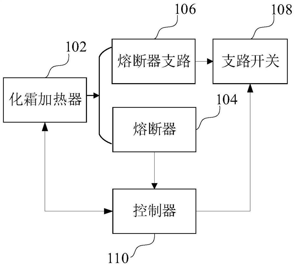
[0056] In one embodiment, such as figure 1 As shown, a refrigeration device is provided, referring to figure 1It can be seen that the refrigeration equipment includes: a defrosting heater 102, a fuse 104 connected in series with the defrosting heater 102, a fuse branch 106 connected in parallel with the fuse 104, a branch switch 108 arranged on the fuse branch 106 and controller 110, wherein:

[0057] The defrost heater 102 is connected in series with the fuse 104, the fuse 104 is connected in parallel with the fuse branch 106, the fuse branch 106 is connected in series ...


PUM


Abstract

The invention relates to refrigeration equipment, a refrigeration equipment operation control method and device and a storage medium. The refrigeration equipment comprises a defrosting heater, a fuse connected with the defrosting heater in series, a fuse branch connected with the fuse in parallel and a controller, and a branch switch on the fuse branch is connected with the controller. The controller is connected with the branch switch on the fuse branch, the fuse and the defrosting heater, when it is detected that the fuse is fused in the defrosting quit state of the refrigeration equipment, the controller controls the branch switch on the fuse branch to be closed, and the fuse branch is connected with the defrosting heater in series. In the refrigeration equipment, the fuse branch is connected with the defrosting heater in series, so that when the fuse is fused and cannot work continuously, the branch switch on the fuse branch connected with the fuse in parallel can be controlled to be closed, the refrigeration work of the refrigeration equipment can be continuously maintained through the fuse branch connected in parallel, the storage temperature of the refrigeration equipment meets the food storage requirement, food decay is avoided, and the refrigeration work efficiency is improved.

Description

technical field [0001] The present application relates to the technical field of electrical equipment control, and in particular to a refrigeration equipment, a refrigeration equipment operation control method, a device, and a storage medium. Background technique [0002] With the development of electrical equipment control technology and the wide application of different types of electrical equipment, such as refrigerators and other refrigeration equipment, in people's work and life, the cooling efficiency requirements for refrigerators and other refrigeration equipment are increasing. At present, the refrigeration principle of air-cooled refrigerators is to distribute the cooling capacity of the evaporator chamber to each compartment through the air ducts through the refrigeration fan, and because the surface temperature of the evaporator is too low, the return air of the compartments will continuously bring the moisture into the compartments. In the evaporator chamber, mo...

Claims


Application Information

Patent Timeline
Patent Type & Authority Applications(China)
IPC IPC(8): F25D11/00F25D29/00F25D21/00
CPCF25D11/00F25D29/003F25D21/002F25D29/008F25D2600/02F25D2600/06Y02B40/00
Inventor 蔡梦婕李琦徐文山
Owner GREE ELECTRIC APPLIANCES INC
Why Eureka
Try Eureka