
Real-time focusing and centering adjustment method and device for in-situ test platform

An in-situ testing and real-time focusing technology, applied in the direction of measuring devices, instruments, scientific instruments, etc., can solve the problems that the optical microscope cannot automatically focus, follow the focus and track the sample, and achieve the effect of solving the sample out of focus and the deviation of the observation area

Active Publication Date: 2022-01-07
WUHAN UNIV
View PDF11 Cites 3 Cited by
  • Summary
  • Abstract
  • Description
  • Claims
  • Application Information

AI Technical Summary

Problems solved by technology

[0006] The invention provides a real-time focusing and centering adjustment method and device for an in-situ testing platform, which combines the in-situ testing technology with an optical microscope to solve the problem that ordinary optical microscopes cannot automatically focus, follow focus and track samples, so that In situ testing technique works well in light microscopy

Method used


Image

  • Real-time focusing and centering adjustment method and device for in-situ test platform
  • Real-time focusing and centering adjustment method and device for in-situ test platform
  • Real-time focusing and centering adjustment method and device for in-situ test platform

Examples


Embodiment 1

[0077] Embodiment 1 provides a real-time focusing and centering adjustment method facing the in-situ test platform. Before the in-situ test, the three-dimensional mobile platform is placed on the position of the stage in the optical microscope, and the three-dimensional mobile platform is installed above the three-dimensional mobile platform. To test the platform and samples in situ, connect the digital camera to the eyepiece of the optical microscope, and connect the host computer to the display screen, the digital camera, and the three-dimensional mobile platform respectively.

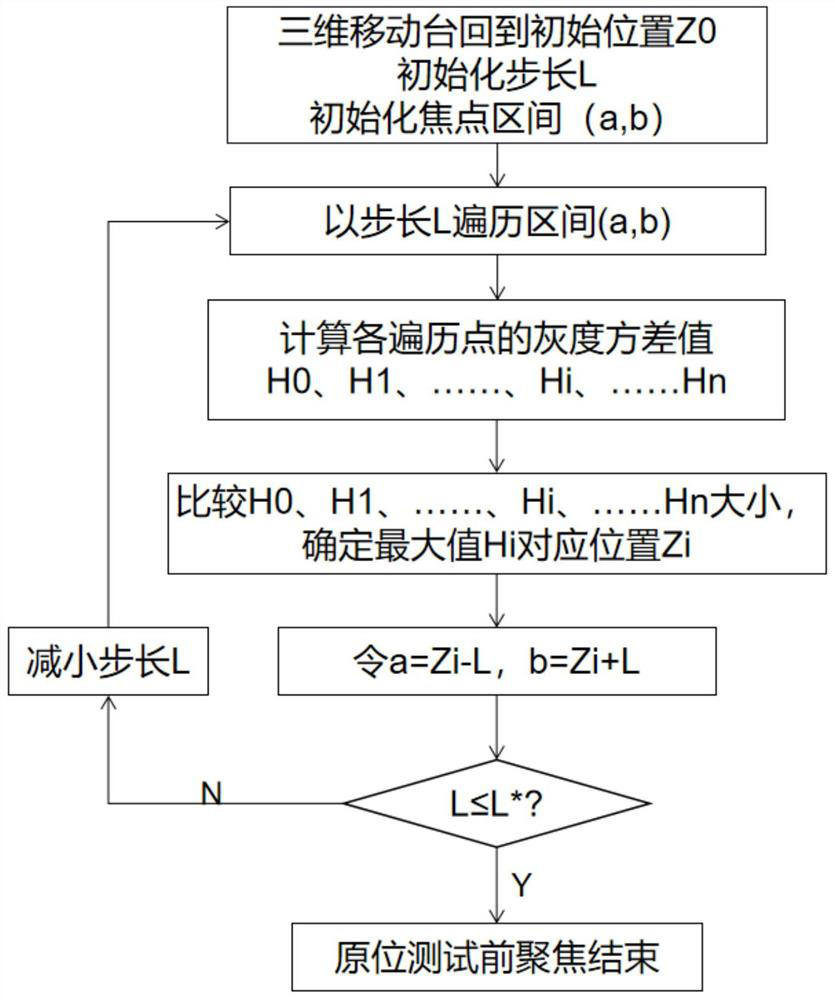
[0078] Before the in-situ test, the host computer executes the pre-test autofocus algorithm to obtain the first control information, and the three-dimensional mobile station controls the sample to move according to the first control information to obtain a clear sample image. The sample image frames the region of interest on the sample.

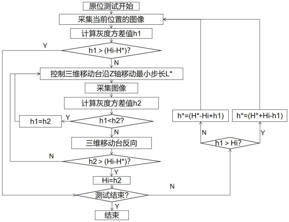
[0079]During the in-situ test, the host executes the in-situ t...

Embodiment 2

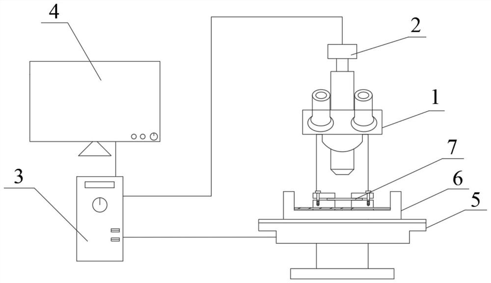
[0137] Embodiment 2 provides a real-time focusing and centering adjustment device for an in-situ test platform, see figure 1 , including: an ordinary optical microscope 1, a digital camera 2, a host computer 3, a display screen 4, a high-precision three-dimensional mobile platform 5 and an in-situ test platform 6. The three-dimensional mobile stage 5 is arranged at the position of the stage in the optical microscope 1, and the top of the three-dimensional mobile stage 5 carries the in-situ test platform 6 and the sample 7; the digital camera 2 and the optical microscope 1, the host computer 3 is connected to the display screen 4, the digital camera 2, and the three-dimensional mobile platform 5 respectively.

[0138] The optical microscope 1 is used to image the sample 7 through an optical system. The digital camera 2 is used to capture the image formed by the optical microscope 1 in real time, and transmit the image information to the host computer 3 . The host 3 includes a...


PUM


Abstract

The invention belongs to the technical field of microscopic observation and discloses a real-time focusing and centering adjustment method and device for an in-situ test platform. According to the method and device, an automatic focusing algorithm and an automatic tracking algorithm are applied to the combination of a common optical microscope and an in-situ technology, automatic focusing in the in-situ test process is realized through an automatic focusing algorithm unit in a host, and automatic tracking of the region of interest is realized through a tracking algorithm unit in the host; problems of defocusing of a tested sample and deviation of an observation area in the in-situ test of the optical microscope can be well solved.

Description

technical field [0001] The invention belongs to the technical field of microscopic observation, and more specifically relates to a real-time focusing and centering adjustment method and device for an in-situ testing platform. Background technique [0002] Traditional material performance testing, including tensile testing, compression testing, torsion testing, shear testing, bending testing, fatigue testing, and creep testing, etc., all use ex-situ testing techniques, that is, before material performance testing or After the performance test, the microscopic morphology of the fracture or surface is observed and analyzed by SEM, TEM, EBSD, XRD and other observation equipment, and the deformation process and microscopic damage mechanism of the material are reasonably guessed and analyzed based on the macroscopic performance test data. reasoning, but lacks direct and powerful graphic proof. With the development of science and technology, people have an urgent need for the micr...

Claims


Application Information

Patent Timeline
Patent Type & Authority Applications(China)
IPC IPC(8): G01N21/01G01N21/84
CPCG01N21/01G01N21/84G01N2021/0112
Inventor 陈志文黄伟刘俐刘胜
Owner WUHAN UNIV
Learn More