
Liquid distributor

A liquid distributor and liquid technology, applied in chemical instruments and methods, feeding devices, chemical/physical processes, etc., can solve the problems of fixed injection height and angle, and save installation space.

Pending Publication Date: 2022-01-14
ZHANGHUAJI SUZHOU HEAVY EQUIP CO LTD
View PDF1 Cites 0 Cited by
  • Summary
  • Abstract
  • Description
  • Claims
  • Application Information

AI Technical Summary

Problems solved by technology

The defect of this kind of liquid distributor is: because the one-way nozzle is directly arranged on the water ring pipe, so limited by the structure of the water ring pipe, the height and angle that the liquid in the water ring pipe can be sprayed are relatively fixed.

Method used


Image

  • Liquid distributor
  • Liquid distributor
  • Liquid distributor

Examples


Embodiment Construction

[0020] A liquid distributor according to the present invention will be further described in detail through specific examples below.

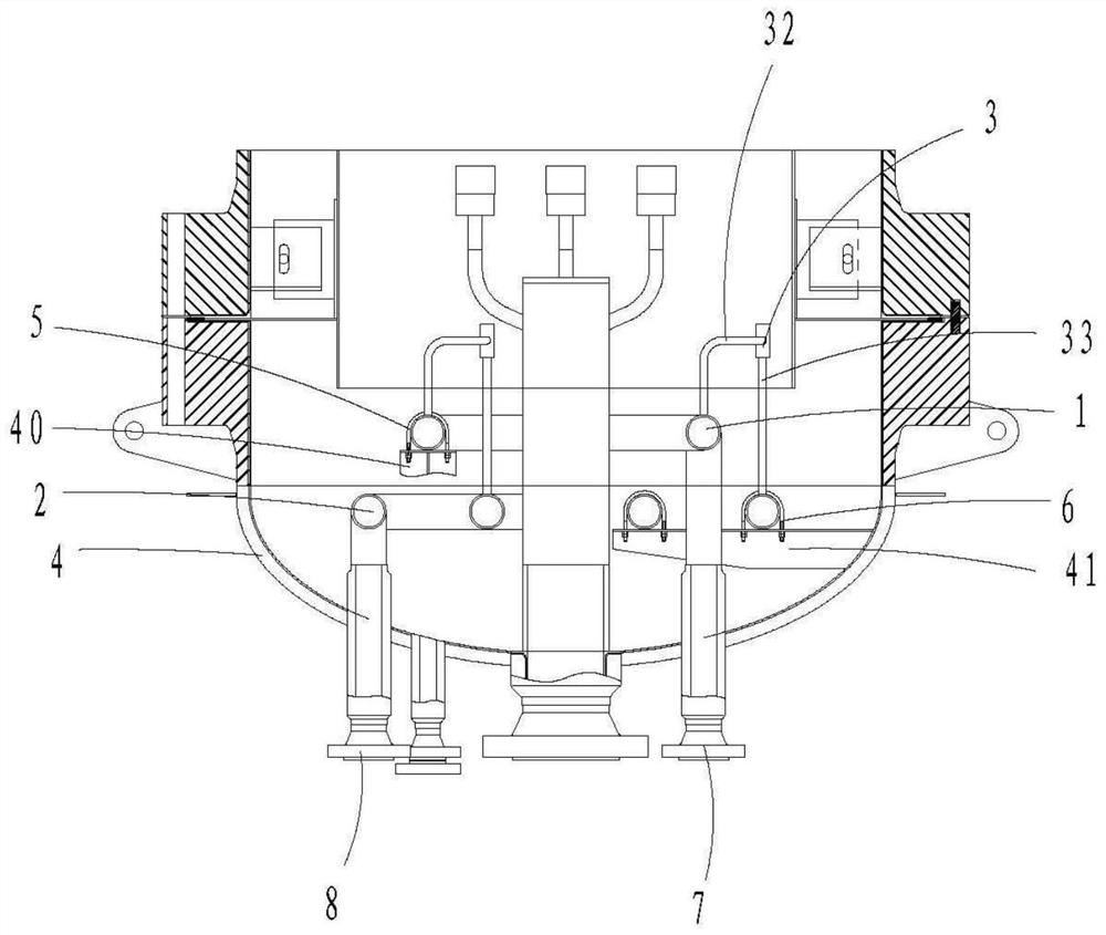
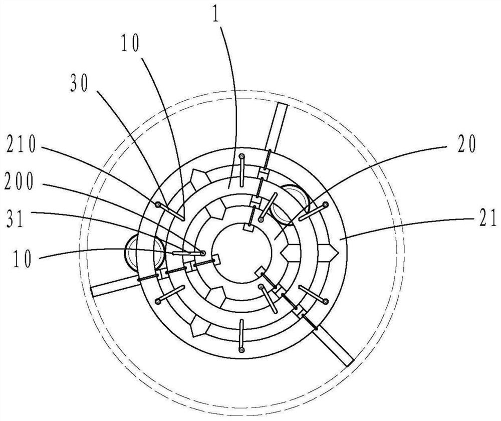
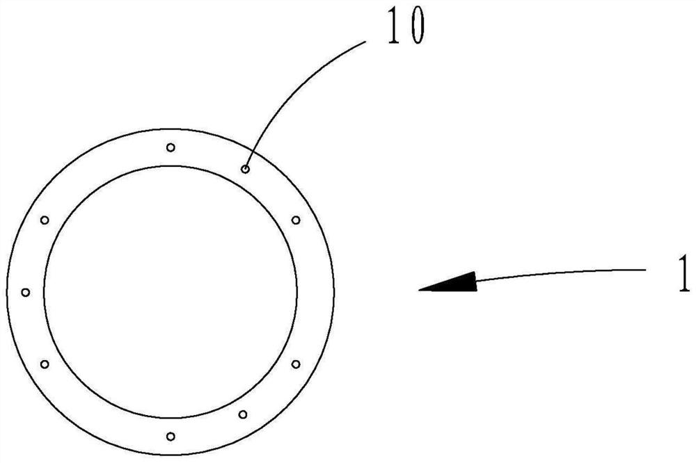
[0021] ginseng Figure 1 to Figure 5 As shown, a liquid distributor includes: an upper distribution ring pipe 1, a lower distribution ring pipe 2 and nine sets of row core pipe assemblies 3, and three uniformly arranged first connecting pieces are welded on the inner wall of the cylinder body 4 40 and three evenly arranged second connectors 41, the upper distribution ring pipe 1 is respectively installed on the three first connectors 40 through three first fixing parts 5, and the lower distribution ring pipe 2 is installed on the three first connectors 40 through three The two second fixing parts 6 are mounted on the three second connecting parts 41 respectively. In this embodiment, the first fixing parts 5 and the second fixing parts 6 are both U-shaped bolts and nuts.

[0022] The upper distribution ring pipe 1 is connected with the liquid in...


PUM


Abstract

The invention relates to a liquid distributor which comprises an upper distribution ring pipe, a lower distribution ring pipe and a plurality of branch core pipe assemblies, the upper distribution ring pipe is connected with a liquid inlet pipe, the lower distribution ring pipe is connected with a compressed air inlet pipe, and the lower distribution ring pipe comprises an inner ring pipe, an outer ring pipe and a radial pipe; a plurality of liquid outlet holes are formed in the upper distribution ring pipe, a plurality of compressed air outlet holes are formed in the lower distribution ring pipe, and each group of branch core pipe assembly is correspondingly connected with one liquid outlet hole and one compressed air outlet hole; each group of branch core pipe assembly comprises a first branch core pipe connected with the liquid outlet hole and a second branch core pipe connected with the compressed air outlet hole; and the free tail end of the first branch core pipe and the free tail end of the second branch core pipe are converged, so that liquid in the first branch core pipe is sprayed out by compressed air in the second branch core pipe, and the spraying height and the spraying position of the liquid can be adjusted according to specific working conditions.

Description

【Technical field】 [0001] The invention relates to the field of chemical machinery, in particular to a liquid distributor. 【Background technique】 [0002] The reaction vessel refers to the vessel used to complete the physical reaction and chemical reaction of the medium. In industrial production, especially in the chemical, pharmaceutical, chemical fertilizer, refining and chemical industries, the reaction vessel is widely used as a pressure-bearing equipment due to technological needs. [0003] The liquid distributor is a commonly used internal part in the reaction vessel. Its function is to distribute the liquid in the reaction vessel. Please refer to Chinese Patent No. 201920969395.4, which discloses a liquid-solid denitrification flow for deep denitrification The liquid distributor of the chemical bed includes a number of water ring pipes arranged concentrically and a number of liquid distribution pipes radially connected to the water ring pipes. The water ring pipes and ...

Claims


Application Information

Patent Timeline
Patent Type & Authority Applications(China)
IPC IPC(8): B01J4/00
CPCB01J4/00
Inventor 郭允杰朱斌王胜
Owner ZHANGHUAJI SUZHOU HEAVY EQUIP CO LTD
Learn More