Urea injection system for reducing NOx discharge of engine and control method thereof

A technology of urea injection system and control method, which is applied in the field of engine exhaust purification system, can solve the problems of no thawing measures, no energy storage, no blockage, etc., and achieve the effect of preventing blockage and eliminating urea freezing

Inactive Publication Date: 2012-10-24
天津思凯汽车环保科技有限公司
View PDF11 Cites 26 Cited by
  • Summary
  • Abstract
  • Description
  • Claims
  • Application Information

AI Technical Summary

Problems solved by technology

[0009] At present, there are vehicle exhaust SCR post-treatment urea injection systems that can meet the above requirements, such as the urea injection system developed by PUREM disclosed in DE102006040411A1, the SCR system of Siemens disclosed in US6209315B1, including the Granite used in the domestic market. Fu company and German Bosch company's systems, some of which use gas-assisted injection, are more ingenious in design and have better atomization effects, but the above are all foreign systems, and the design and manufacturing costs of components are very high, which is not conducive to SCR systems Large-scale promotion in the country
Similar systems have also appeared in China in recent years, including the SCR urea injection system developed by the Wuxi Oil Pump Nozzle Research Institute disclosed in CN101737127A, and the quantitative injection device of Suzhou Paigeli Emission Reduction System Co., Ltd. disclosed in CN101818677A. It is too perfect, but there are some problems. For example, the scheme of thawing with the help of engine exhaust mentioned in the former system is not easy to realize control; The designed passive pressure stabilizing airbag cannot play the role of energy storage when the gas source is turned off, and cannot effectively return when the system is turned off, and there is no thawing measure, which cannot solve the problem of urea freezing at low temperature

Method used


Image

  • Urea injection system for reducing NOx discharge of engine and control method thereof
  • Urea injection system for reducing NOx discharge of engine and control method thereof
  • Urea injection system for reducing NOx discharge of engine and control method thereof

Examples


Embodiment Construction

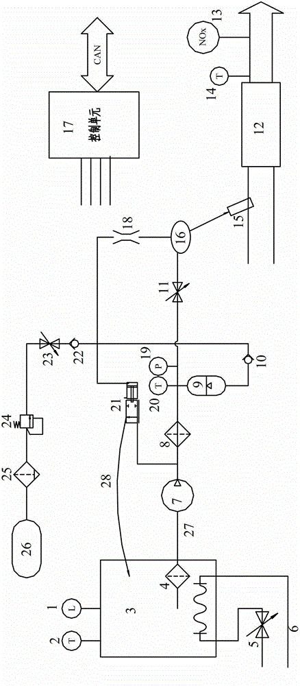
[0046] A urea injection system for reducing engine NOx emissions in the present invention mainly includes a urea supply unit, an injection unit, a thawing unit and a control unit. The technical solution of the present invention will be further described in detail below in conjunction with the accompanying drawings.

[0047] like Figure 1-2 As shown, the urea supply unit in the system of the present invention mainly includes a urea DC pump 7, a secondary filter 8, an accumulator 9, a urea return air control valve 21, and a second one-way valve for air circuit control 22 and the second solenoid valve 23, the first solenoid valve 11 for urea supply control, the gas-liquid mixer 16, the pressure sensor 19 and the second temperature sensor 20 for monitoring the pressure and temperature of urea in the pipeline, etc.

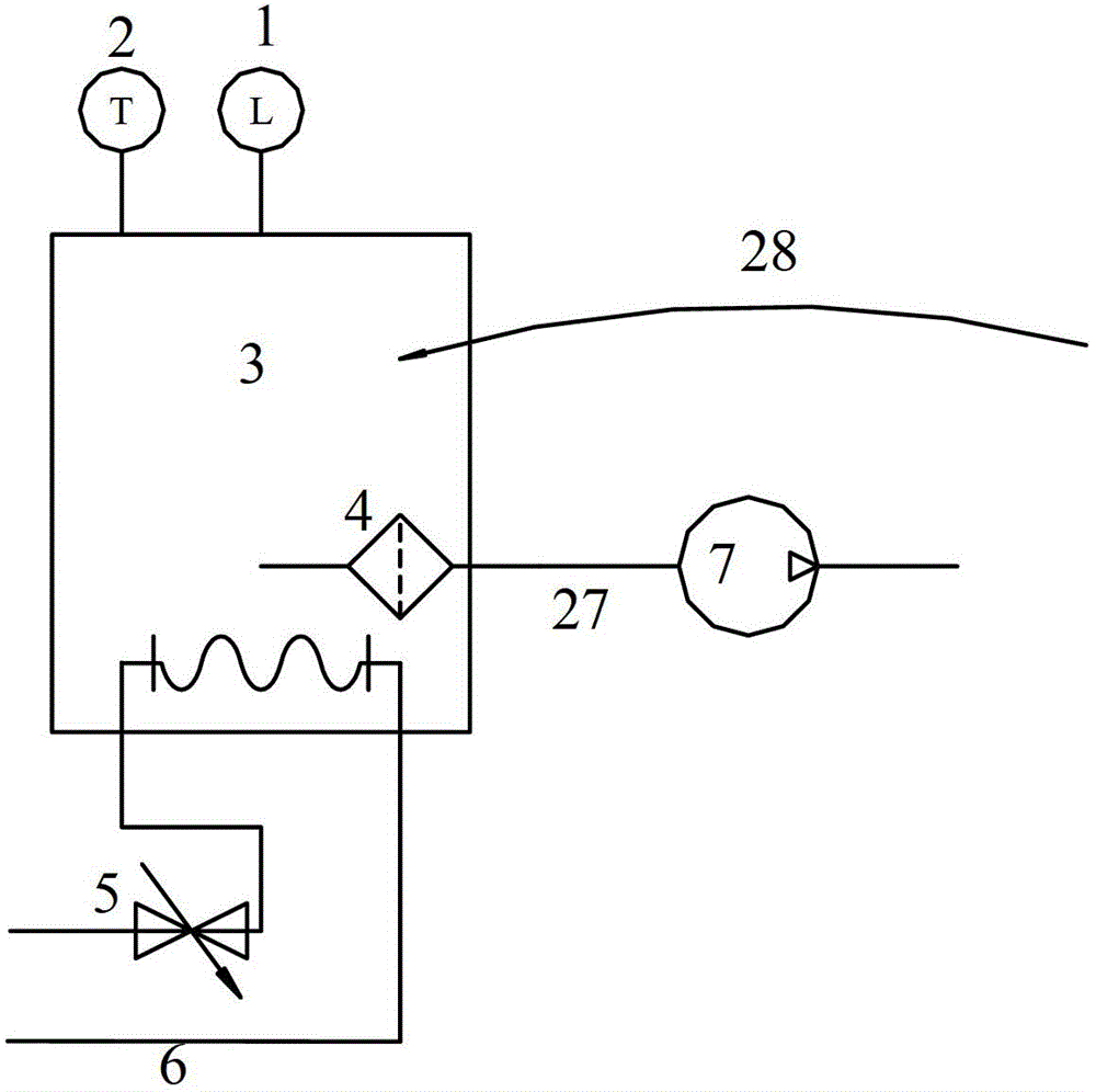
[0048] like Picture 1-1 , the urea tank 3 is sequentially connected to the urea tank 3 through the first pipeline 27, the urea DC pump 7, the secondary filter 8, the...


PUM


Abstract

The invention discloses a urea injection system for reducing the NOx discharge of an engine. The urea injection system mainly comprises a urea supply unit, an injection unit, an unfreezing unit and a control unit. The urea supply unit comprises a urea unidirectional flow pump, a secondary filter, a first electromagnetic valve and a gas liquid mixer which are sequentially connected with a urea tank by a first pipeline; and a spray nozzle part in the injection unit is used for spraying the gas liquid mixture into an exhaust pipeline communicated with the upstream of an SCR (Selective Catalytic Reduction) catalyst; according to the system disclosed by the invention, urea is sucked out of the urea tank and a certain pressure is formed, the injection quantity of the urea is automatically regulated according to the operation working condition of the engine, and the urea is sprayed into the exhaust pipe of the engine after the urea is atomized by high pressure air so as to react with NOx discharged from the engine on the SCR catalyst, and thus, the aim of reducing the NOx discharge is fulfilled; and the control unit is communicated with an engine controller to coordinate the normal work of the integral system and monitor the working conditions of the system and the parts.

Description

technical field [0001] The invention relates to an engine exhaust purification system, in particular to a urea injection system for reducing engine NOx emissions. Background technique [0002] With the rapid growth of China's automobile production and ownership, the problem of automobile exhaust pollution is becoming more and more serious. In order to deal with this prominent problem, the country has successively issued automobile emission standards and regulations at different stages, and various automobile and engine companies have also gradually adopted automobile engines. Corresponding technical measures have been taken to meet the gradually tightening emission regulations. In terms of diesel engines for heavy-duty vehicles, before and after China III emission standards, internal measures are basically adopted to achieve the goal, such as using high-pressure common rail, increasing fuel injection pressure, precisely controlling fuel injection time and angle, using exhaus...

Claims


Application Information

Patent Timeline
Patent Type & Authority Applications(China)
IPC IPC(8): F01N3/20F01N9/00
CPCY02T10/47Y02A50/20Y02T10/40
Inventor 龙顺洪王蒸董建赵中煜吴建梁杨国焱
Owner 天津思凯汽车环保科技有限公司
Why Eureka
Try Eureka