Base of detection device and processing method thereof

A technology of a detection device and a processing method, which is applied to electromagnetic measurement devices, electric/magnetic diameter measurement, etc., can solve problems such as low efficiency

Active Publication Date: 2022-01-14
CHENGDU AIRCRAFT INDUSTRY GROUP
View PDF12 Cites 0 Cited by
  • Summary
  • Abstract
  • Description
  • Claims
  • Application Information

AI Technical Summary

Problems solved by technology

[0003] The present invention aims at the problem that the efficiency of the existing measuring device is low when it is artificially judged whether the measuring tool is in the minimum state in the axial direction and the maximum state in the radial direction. The specific technical scheme is as follows:

Method used


Image

  • Base of detection device and processing method thereof
  • Base of detection device and processing method thereof
  • Base of detection device and processing method thereof

Examples


Embodiment 1

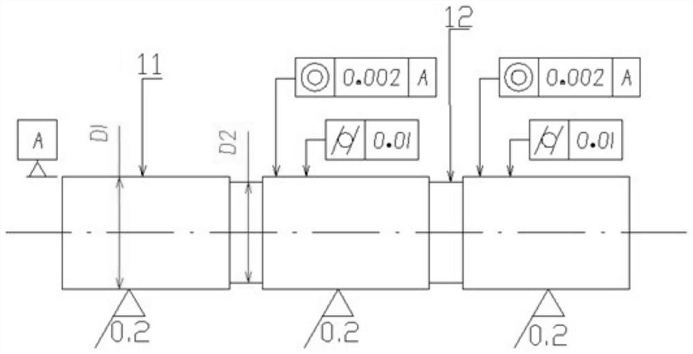
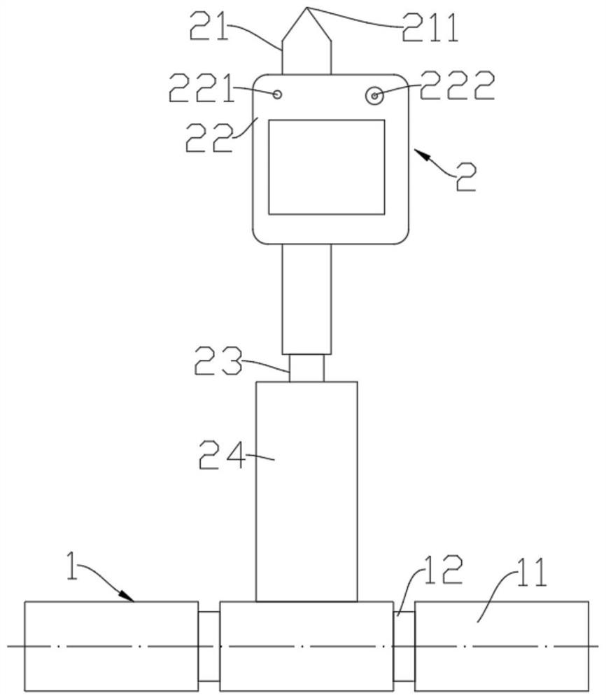
[0036] Please refer to figure 1 , figure 2 , the present embodiment provides a base of a detection device, including n+1 conductive segments 11 and n insulating segments 12, the conductive segment is a cylinder, n≥2, and n is an even number; it also includes a display device, The display device includes a display lamp 221, and n+1 conductive segments control the state of the display lamp through a control circuit; the control circuit includes an AND gate, a power supply, and two optocouplers, and the first input terminals of the two optocouplers are connected to the positive pole of the power supply , the second input terminals of the two optocouplers are respectively connected to the conductive segments at both ends, the negative pole of the power supply is connected to the conductive segment in the middle, the first output terminals of the two optocouplers are connected to each other and grounded, and the second terminals of the two optocouplers The output end is connected...

Embodiment 2

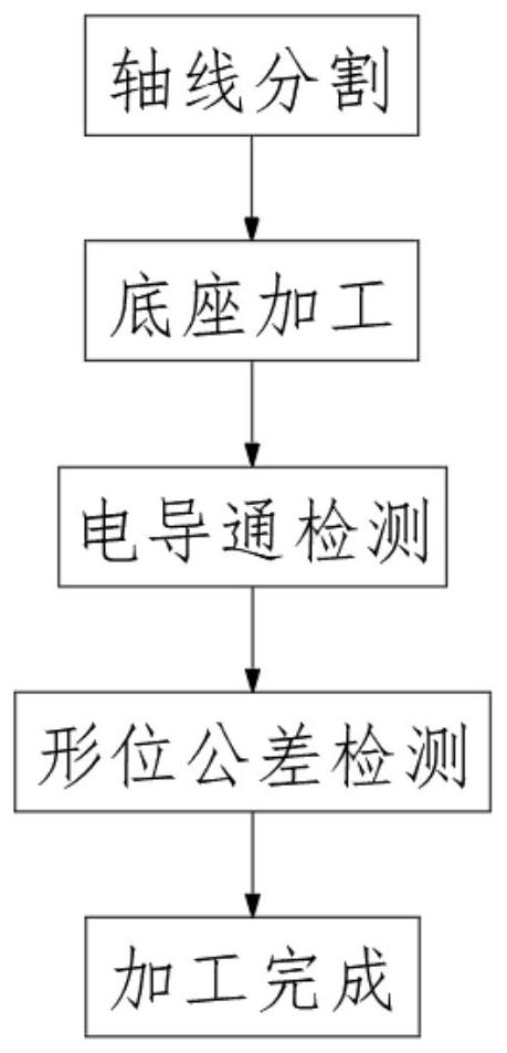
[0048] Please refer to Figure 1-Figure 4 , the present embodiment provides a processing method for processing the base of the detection device described in Embodiment 1, comprising the following steps:

[0049] Axis division: according to the axial length of the measured hole, the axis of the base 1 of the detection device is divided into a plurality of conductive segments 11 and a plurality of insulating segments 12;

[0050] Base processing: connect n+1 conductive segments 11 and n insulating segments 12 to process into base 1;

[0051] Electrical conduction detection: use a conductive detection device to conduct a conductive detection experiment on the processed base 1;

[0052] Geometric tolerance detection: detect the geometrical tolerance of the base 1 after processing, including the surface roughness of the base 1, the coaxiality of the cylindricity of the outer circle, and the perpendicularity between the two ends of the outer circle and the axis;

[0053] After the...


PUM


Abstract

The invention discloses a base of a detection device, which comprises a plurality of conductive sections and a plurality of insulating sections, wherein one insulating section is connected between every two conductive sections; and also comprises a display lamp which is controlled by the plurality of conductive sections through a control circuit; the control circuit comprises an AND gate, a power supply and two optocouplers, two input ends of the two optocouplers are respectively connected with a positive electrode of the power supply and the conductive section at the end part, a negative electrode of the power supply is connected with the conductive section at the middle part, first output ends of the two optocouplers are connected with each other and then grounded, second output ends of the two optocouplers are connected with two input ends of the AND gate, the output end of the AND gate is grounded after being connected with the display lamp; the invention further provides a processing method which is used for processing the base and comprises the steps of axis segmentation, base machining, electric conduction detection, form and location tolerance detection and the like. According to the invention, not only is the working efficiency improved, but also misjudgment can be caused only by manual judgment, so that the scheme also reduces errors in the subsequent measurement process.

Description

technical field [0001] The invention relates to the technical field of detection devices, in particular to a base of a detection device and a processing method thereof. Background technique [0002] In the aircraft manufacturing process, the measurement of the diameter of some large holes (generally ≥ 150mm) is involved. The current measurement method is generally a single inner diameter micrometer. In the process of using a single inner diameter micrometer to measure, manual repeated measurements are required. To record, it is necessary to manually judge whether the measuring tool is in the axial minimum and radial maximum state during measurement. Relying on manual judgment of the diameter direction makes the measurement efficiency low and the error large. Especially in the measurement of the large parts of the aircraft after the finish machining of the butt joint hole, there is still a complex measurement environment, which makes it difficult for the existing measurement...

Claims


Application Information

Patent Timeline
Patent Type & Authority Applications(China)
IPC IPC(8): G01B7/13
CPCG01B7/13
Inventor 陈代鑫周力韩利亚缑建杰
Owner CHENGDU AIRCRAFT INDUSTRY GROUP
Why Eureka
Try Eureka