
Closed storage battery vacuumizing formation device

A chemical formation device and storage battery technology, applied in the direction of lead-acid batteries, lead-acid battery construction, battery pack components, etc., can solve the problem of low acid addition efficiency of batteries, achieve the effect of improving acid addition efficiency and improving acid addition efficiency

Pending Publication Date: 2022-01-14
浙江集秀元智能装备有限公司
View PDF1 Cites 0 Cited by
  • Summary
  • Abstract
  • Description
  • Claims
  • Application Information

AI Technical Summary

Problems solved by technology

[0005] The purpose of the present invention is to provide a sealed storage battery vacuum formation device, which forms a closed chamber by enclosing the sealed box and the bottom plate, and forms a negative pressure in the sealed chamber through a vacuum pump, so as to realize synchronous vacuuming of the storage battery inside the sealed chamber It solves the problem of low acid addition efficiency of existing batteries

Method used


Image

  • Closed storage battery vacuumizing formation device
  • Closed storage battery vacuumizing formation device
  • Closed storage battery vacuumizing formation device

Examples


Embodiment 1

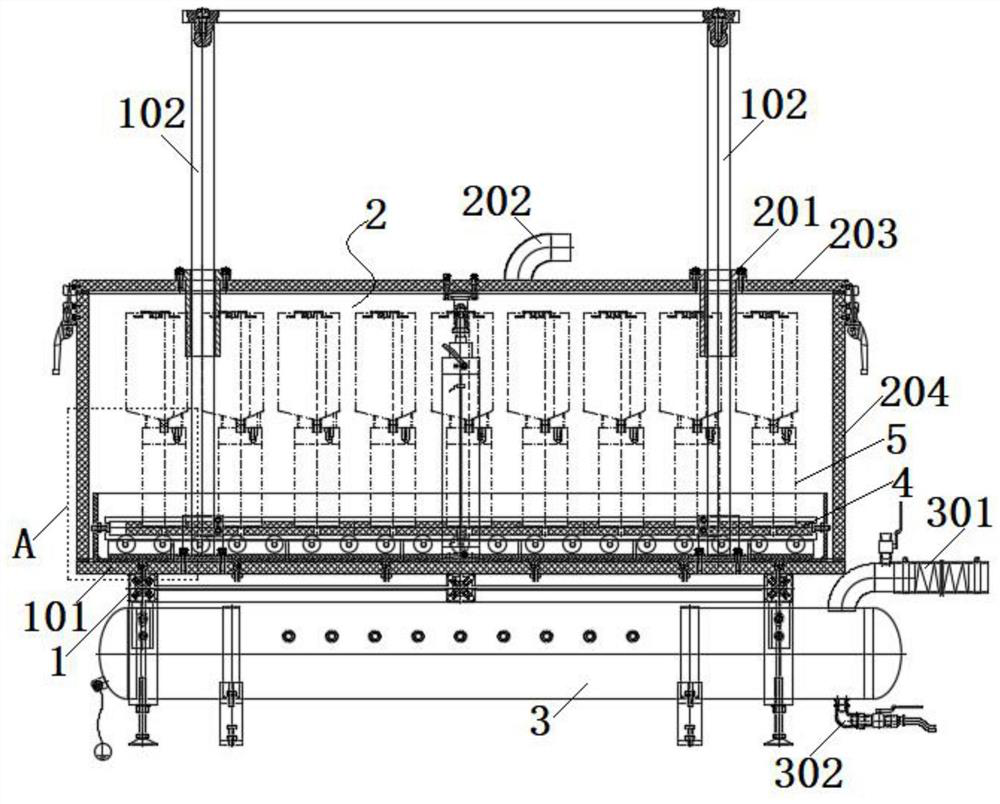
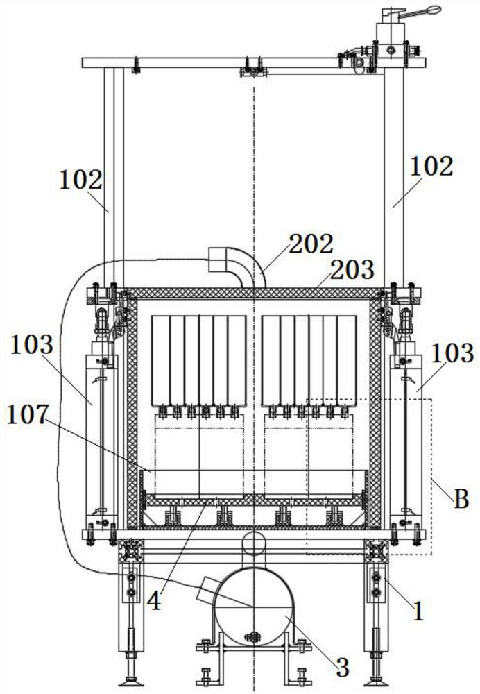
[0029] see Figure 1-4 As shown, the present invention is a vacuum forming device for a sealed storage battery, including a frame 1 , a sealed box 2 and a transfer tank 3 . The frame 1 is fixedly connected with a base plate 101 by welding or bolts; the upper surface of the base plate 101 is fixedly connected with two to four pairs of guide rods 102 and telescopic mechanisms 103, and the telescopic mechanisms 103 are air cylinders or hydraulic cylinders or electric telescopic rods.

[0030] The sealing box 2 is a box structure with an open bottom; the sealing box 2 is connected with a guide sleeve 201 cooperating with the guide rod 102, and the sealing box 2 is connected with the telescopic mechanism 103, which is used to drive the sealing box 2 to move up and down through the telescopic mechanism 103, And when the lower surface of the sealing box 2 is attached to the upper surface of the bottom plate 101, the sealing box 2 and the bottom plate 101 are enclosed to form a closed...

Embodiment 2

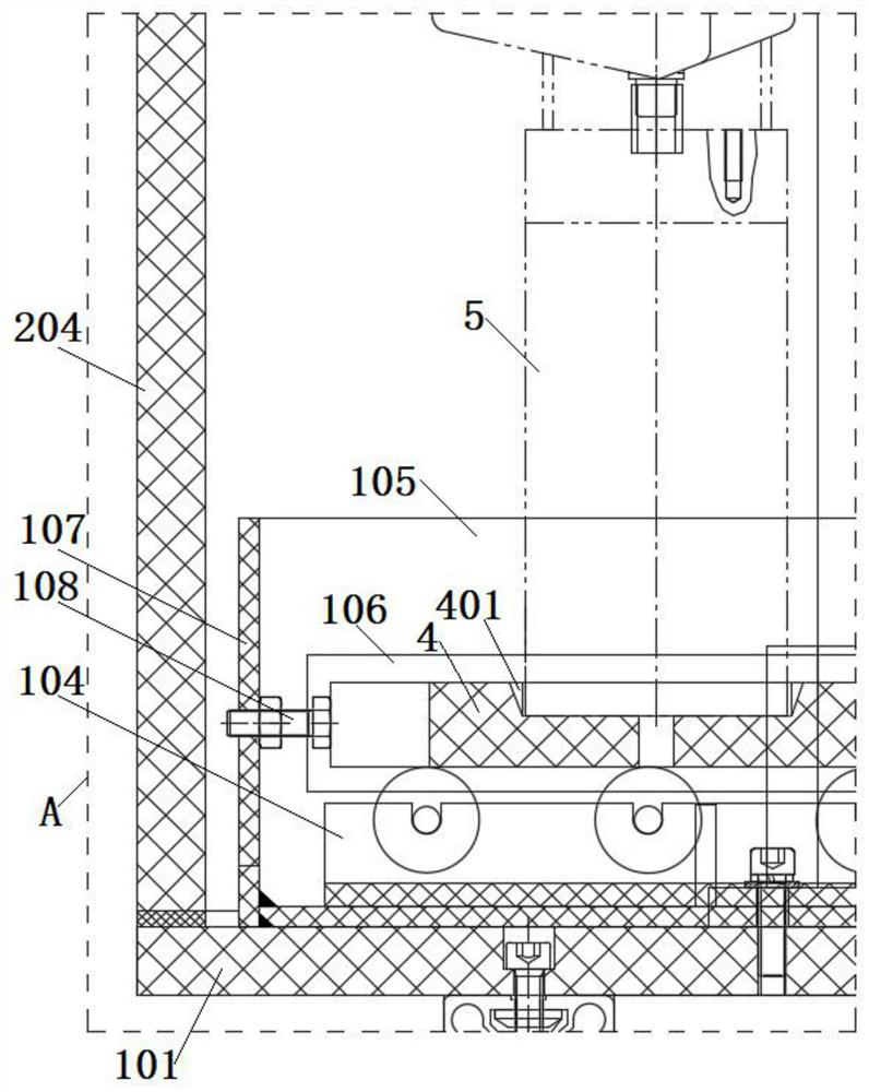
[0038] On the basis of Embodiment 1, a tray 4 is provided on the upper surface of the bottom plate 101, and several positioning grooves 401 distributed in pairs are opened on the upper surface of the tray 4, which are used to put the battery into the positioning groove 401, and the battery can be aligned through the positioning groove 401. Limit the location. By putting the accumulator 5 in acid addition into the positioning groove 401, multiple accumulators 5 can be transported and moved synchronously through the tray 4, which is beneficial to improve the convenience of use and production efficiency. Wherein, the inner bottom surface of the positioning groove 401 is provided with a through hole 402, through which the foreign matter or waste liquid accumulated in the positioning groove 401 can be removed to avoid accumulating in the positioning groove 401 and contaminating the battery.

[0039] At the same time, the upper surface of the bottom plate 101 is provided with two to...


PUM


Abstract

The invention discloses a closed storage battery vacuumizing formation device, and relates to the technical field of storage battery production. The device comprises a rack, a sealing box and a transfer tank, wherein the rack is connected with a bottom plate; the bottom plate is connected with a guide rod and a telescopic mechanism; the sealing box is connected with a guide sleeve matched with the guide rod, the sealing box is connected with the telescopic mechanism and used for driving the sealing box to move up and down through the telescopic mechanism, and when the sealing box is attached to the bottom plate, a closed cavity is defined by the sealing box and the bottom plate; a connecting pipe is connected to the outer wall of the sealing box and communicated with the interior of the sealing box; the transfer tank is communicated with the connecting pipe through a pipeline; the upper part of the transfer tank is connected with an adapter pipe, and the bottom part is connected with a drain valve; and the adapter pipe is connected with a negative pressure pump. The closed chamber is defined by the sealing box and the bottom plate, negative pressure is formed in the sealed chamber through the vacuum pump, synchronous vacuumizing treatment on the storage battery in the sealed chamber is achieved, and the problem that the acid adding efficiency of an existing storage battery is low is solved.

Description

technical field [0001] The invention belongs to the technical field of storage battery production, in particular to a vacuum forming device for a sealed storage battery. Background technique [0002] When adding acid to the lead-acid battery, use the acid adding machine to inject acid solution into the acid adding pot connected with the lead-acid battery, and then add acid to the lead-acid battery through the acid adding pot. However, due to the small internal space of the lead-acid battery, the air in the lead-acid battery cannot be completely discharged during the acid addition process, and it cannot be guaranteed that the acid solution in the acid addition pot cannot be completely poured into the lead-acid battery, so that the lead-acid battery will appear when it is formed. The formation is not uniform and the compounding rate is lowered. [0003] In order to solve the above-mentioned problem of incomplete acid addition to the storage battery, the acid addition pot is u...

Claims


Application Information

Patent Timeline
IPC IPC(8): H01M50/618H01M50/673H01M10/12
CPCH01M50/618H01M50/673H01M10/12Y02E60/10Y02P70/50
Inventor 韩峰李海彪陈彦行邓建军赵月康马冲蒋超
Owner 浙江集秀元智能装备有限公司
Learn More