A transmitter and its gain compensation method

A gain compensation and transmitter technology, applied in the electronic field, can solve the problems of poor gain compensation accuracy and difficult to precisely control radio frequency gain, and achieve the effect of accurate temperature gain compensation, simple implementation scheme, and wide gain compensation effect.

Active Publication Date: 2022-05-27
SOUTH CHINA UNIV OF TECH +1
View PDF13 Cites 0 Cited by
  • Summary
  • Abstract
  • Description
  • Claims
  • Application Information

AI Technical Summary

Problems solved by technology

However, the temperature compensation in this publication is only used as a supplement to the automatic gain control to prevent the radio power from exceeding the power limit value at high temperature, and the improvement of the communication standard in the scheme allows +2dB and -4dB changes, not to achieve power at various temperatures precise control of
[0015] In general, among the current existing solutions, some only perform limited compensation through the temperature characteristics of the device, some have poor gain compensation accuracy due to the difficulty in precise control of the RF gain, and some rely on complex digital control and are difficult to operate without signal processing modules. implemented on a radio chip

Method used


Image

  • A transmitter and its gain compensation method
  • A transmitter and its gain compensation method
  • A transmitter and its gain compensation method

Examples


Embodiment Construction

[0044] Below in conjunction with embodiment, the present invention is further described, but does not constitute any limitation to the present invention, and the limited number of modifications done by anyone in the scope of the claims of the present invention are still within the scope of the claims of the present invention.

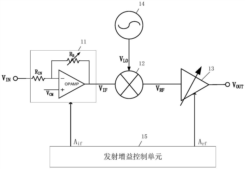
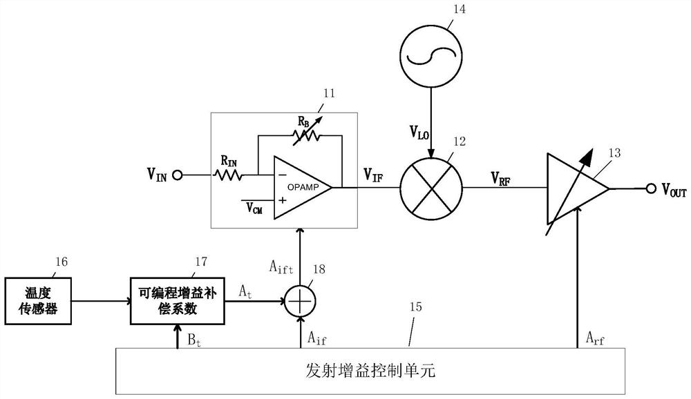
[0045] see Figure 2-Figure 4 , a gain compensation method for a transmitter of the present invention, firstly analyzes the gain temperature rise characteristic of the transmitter, and obtains a programmable gain compensation parameter A t .

[0046] In this embodiment, the gain temperature rise characteristic of the transmitter is analyzed to obtain the programmable gain compensation parameter A t , which includes the following steps:

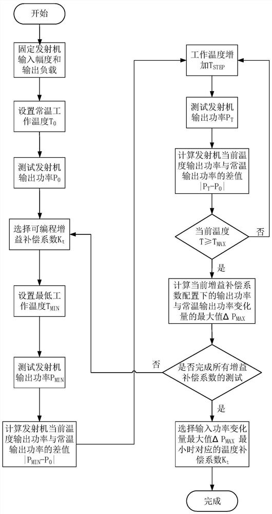
[0047] Step 1. Analyze the temperature rise power characteristics of the transmitter through the minimization analysis method of temperature rise power difference to obtain the temperature gain compensation coefficien...


PUM


Abstract

The invention discloses a gain compensation method for a transmitter, relates to electronic technology, and solves the technical problem that the current gain compensation method for a transmitter has poor accuracy. Analyze the gain temperature rise characteristics of the transmitter to obtain the programmable gain compensation parameter A t ; The programmable gain compensation parameter A t with the IF gain control parameter A if Combined, the IF gain G IF Make compensation. The invention also discloses a transmitter. The implementation scheme of the invention is simple, and more accurate temperature gain compensation of the transmitter can be obtained.

Description

technical field [0001] The present invention relates to electronic technology, and more particularly, to a transmitter and a gain compensation method thereof. Background technique [0002] The RF amplifier of the transmitter processes signals with high frequency, and usually cannot use the closed-loop operation of the operational amplifier to control the gain. In the open-loop mode, the gain of the RF amplifier will be affected by the manufacturing process, supply voltage and temperature changes. [0003] like figure 1 Shown is a traditional direct up-conversion transmitter with variable gain, which generally includes five parts: an intermediate frequency amplifier 11 , an up-converter 12 , a radio frequency amplifier 13 , a local oscillator generating unit 14 and a transmit gain control unit 15 . [0004] Among them, the intermediate frequency amplifier 11 is composed of at least an operational amplifier OPAMP, an input resistor R IN and variable feedback resistor R B co...

Claims


Application Information

Patent Timeline
Patent Type & Authority Patents(China)
IPC IPC(8): H04B1/04G01K13/00
CPCH04B1/04G01K13/00Y02D30/70
Inventor 王日炎李斌贺黉胤吴朝晖张芳芳陈志坚
Owner SOUTH CHINA UNIV OF TECH
Why Eureka
Try Eureka