
Rail transit emergency lighting control circuit

An emergency lighting and rail transit technology, applied in railway vehicle lighting devices, railway car body parts, transportation and packaging, etc. Adjustable time and time, the effect of increasing safety

Pending Publication Date: 2022-01-18
CRRC NANJING PUZHEN CO LTD
View PDF0 Cites 0 Cited by
  • Summary
  • Abstract
  • Description
  • Claims
  • Application Information

AI Technical Summary

Problems solved by technology

[0002] The existing emergency lighting control circuit cannot meet the requirements of unmanned subway vehicles for emergency lighting power supply circuit redundancy and emergency lighting delay after the vehicle is dormant, so it is necessary to design a redundant emergency lighting power supply circuit and emergency lighting delay control circuits that meet the requirements of unmanned vehicles

Method used


Image

  • Rail transit emergency lighting control circuit
  • Rail transit emergency lighting control circuit

Examples


Embodiment Construction

[0012] What follows is an explanation of the embodiments of the present invention.

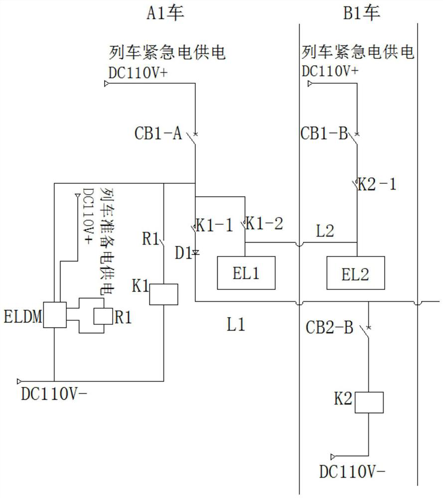
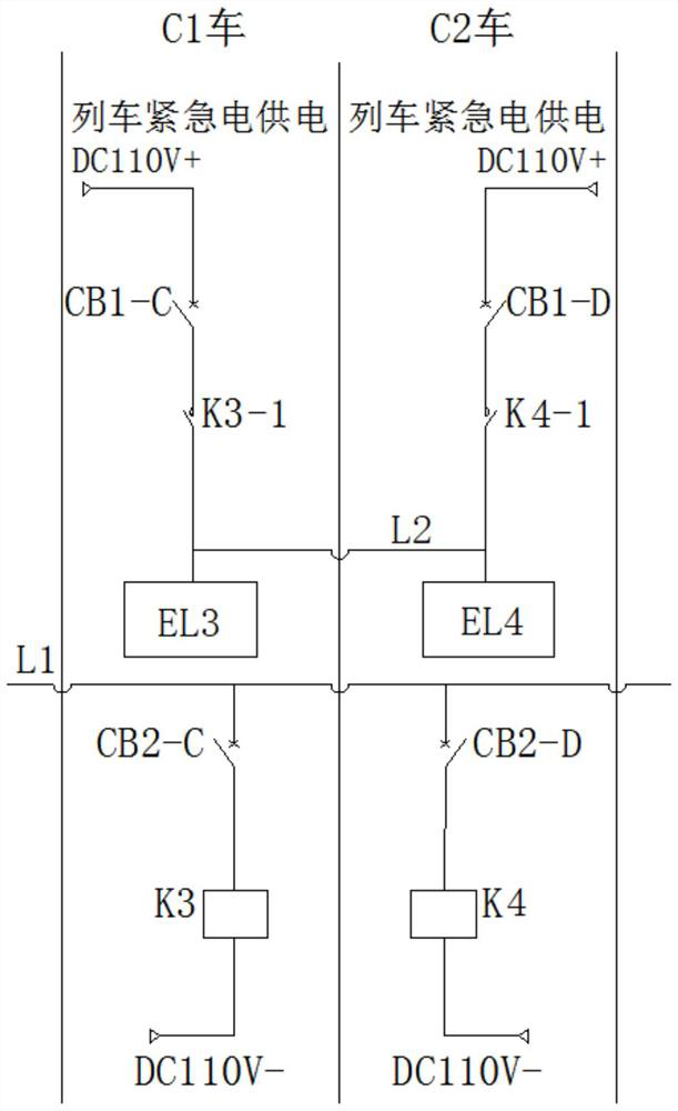
[0013] like figure 1 , figure 2 Shown, respectively, in the schematic portion of the first car and the intermediate car, an intermediate vehicle for the intermediate rail vehicle emergency lighting control circuit. Example rail emergency lighting control circuit of the present invention, comprising: a power supply emergency, and each vehicle is provided by the emergency power supply of the emergency lighting fixture (EL1-El4), through the vehicle train emergency lighting control lines L1, located in the head is controlled by the vehicle power train ready ELDM delay module (delay module also ELDM emergency power supply from the current vehicle), connected to the output of the delay module ELDM relay R1 and the relay R1 is controlled by the head car contactor K1, the emergency lighting control line L1 of the end portion of the train via the first normally open contact K1-1 connector vehicle emergenc...


PUM


Abstract

The invention relates to a rail transit emergency lighting control circuit which comprises an emergency lighting control train line penetrating through a whole vehicle, a time delay module located on a head vehicle and a head vehicle contactor controlled by the time delay module, and the end of the emergency lighting control train line is connected with an emergency power supply of the head vehicle through a first normally open contact of the head vehicle contactor. A second normally open contact of the head car contactor is connected in series with a power supply loop of the head car emergency lighting lamp; the middle train is provided with a middle train contactor connected to an emergency lighting control train line, and a normally open contact of the middle train contactor is connected into a power supply loop of a middle train emergency lighting lamp in series. Every two adjacent vehicles are grouped, and the emergency lighting lamps are connected through the emergency lighting redundant train lines. A pairwise redundant power supply mode is adopted for vehicle emergency lighting power supply, the function of emergency lighting time delay after the whole train is dormant is achieved through an adjustable time delay relay, and the function of short circuit and overload isolation of a downstream control circuit is achieved by additionally arranging a circuit breaker.

Description

Technical field [0001] The present invention relates to a rail vehicle emergency lighting control circuit, belonging to the technical field of emergency lighting rail vehicle. Background technique [0002] Conventional emergency lighting control circuit can not meet emergency vehicle lighting driverless metro Emergency lighting power supply circuit redundancy and sleep latency requirements of the vehicle, and therefore need to design a power supply circuit redundant emergency lighting and emergency lighting delay control circuit, to meet the requirements of the unmanned vehicle. Inventive content [0003] The main object of the present invention is directed to above-mentioned drawbacks of the prior art, there is provided a rail emergency lighting control circuit, the redundant power supply emergency lighting and emergency lighting delay. [0004] To solve the above technical problem, the emergency lighting rail of the present invention provides a control circuit comprising an em...

Claims


Application Information

Patent Timeline
Patent Type & Authority Applications(China)
IPC IPC(8): B61D29/00
CPCB61D29/00
Inventor 孙建屠小娥鄢艳丽庞魏
Owner CRRC NANJING PUZHEN CO LTD
Learn More