Supercharge Your Innovation With Domain-Expert AI Agents!

Cutting and clamping mechanism for wave-shifted optical fibers

A clamping mechanism and optical fiber technology, applied in the direction of conveying filamentous materials, thin material processing, transportation and packaging, etc., can solve the problems of economic loss, brittleness of wave-shifting optical fiber structure, and optical fiber damage.

Active Publication Date: 2022-01-18
INSTITUTE OF SCIENCE & TECHNOLOGY INNOVATION DONGGUAN UNIVERSITY OF TECHNOLOGY
View PDF9 Cites 1 Cited by
  • Summary
  • Abstract
  • Description
  • Claims
  • Application Information

AI Technical Summary

Problems solved by technology

[0002] China's spallation neutron source detectors include scintillator detectors. Existing scintillator detectors need to use wave-shifting optical fibers for detector signal transmission. The price of wave-shifting optical fibers is very expensive. At present, most of them are imported, and the price is about 17 US$ / m, the structure of the wave-shifting fiber is brittle, and it is easy to be bent and damaged, and thus light leakage occurs, which affects signal transmission; during the development of the detector, it is necessary to realize the bending of the wave-shifting fiber. In order to realize the bending of the fiber, The bending carrier is designed, which consists of three sections of plates, and the outer plate can rotate around the middle plate. There are slots for placing wave-shifting optical fibers on the three sections of the plate. The optical fibers need to be placed in the slots, and then Press the locking block on the outer ends of the two outer plates, and then lock them with bolts to realize the discharge of the wave-shifting optical fiber, and realize the bending of the wave-shifting optical fiber through the bending of the bending carrier (generally, water bath bending is used) , the previous wave-shifting optical fibers were cut by manual cooperation with cutting equipment for single or multiple strands, and then the cut wave-shifting optical fibers were manually placed into the bending carrier. In this process, manual Repeated handling of optical fibers can easily cause damage to optical fibers and cause economic losses

Method used


Image

  • Cutting and clamping mechanism for wave-shifted optical fibers
  • Cutting and clamping mechanism for wave-shifted optical fibers
  • Cutting and clamping mechanism for wave-shifted optical fibers

Examples


Embodiment Construction

[0021] In order to enable those skilled in the art to better understand the technical solution of the present invention, the present invention will be described in detail below in conjunction with the accompanying drawings. The description in this part is only exemplary and explanatory, and should not have any limiting effect on the protection scope of the present invention. .

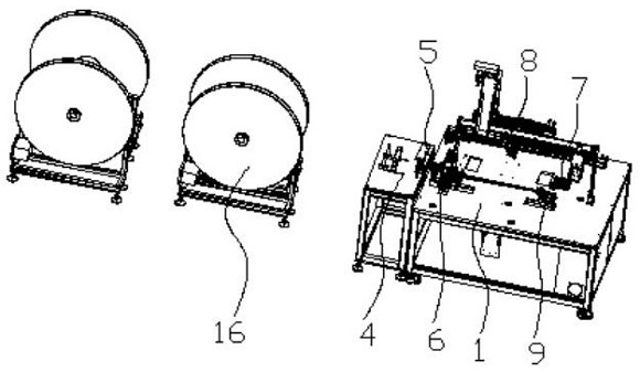
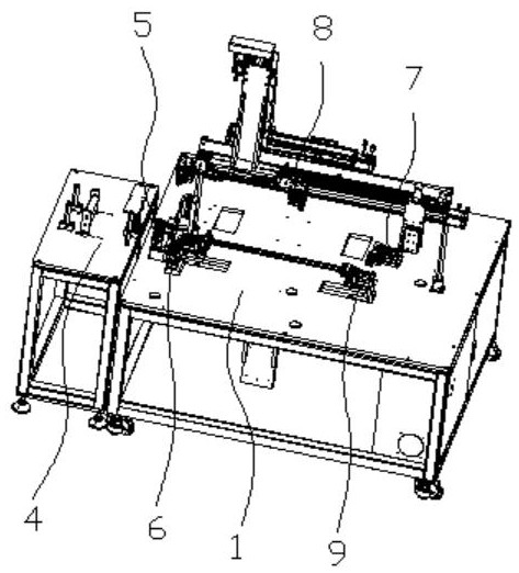
[0022] like Figure 1-Figure 4 As shown, the structure of the present invention is: a cutting and clamping mechanism for a wave-shifting optical fiber, including a frame 1 and an unwinding device 16. The frame 1 is provided with a guiding device 4 that cooperates with the unwinding device 16, The guide device 4 includes a guide frame 105 arranged on the frame 1, the guide frame 105 is provided with a height guide roller 106 and a distance guide roller 107, and the optical fibers 30 released from the unwinding device 16 are all from two heights. The guide roller 106 passes through the middle, and each ...


PUM


Abstract

The invention relates to a cutting and clamping mechanism for wave-shifted optical fibers. The cutting and clamping mechanism comprises a rack, an unwinding device and a guiding device; the guiding device comprises a guiding frame arranged on the rack; height guiding rollers and spacing guiding rollers are arranged on the guiding frame; all the optical fibers unwound from the unwinding device penetrate through the space between the two height guiding rollers, and each optical fiber penetrates through the space between the two adjacent vertical spacing guiding rollers; the rack is further provided with a wire pulling device matched with all the optical fibers penetrating through the spacing guiding rollers; a cutting device is arranged between the wire pulling device and the guiding device; the rack is further provided with a wire clamping device which is matched with the optical fibers pulled out by the wire pulling device and can clamp the single optical fiber; the rack is further provided with a wire unwinding device used for clamping the two ends of the optical fibers clamped by the wire clamping device; and the optical fibers can be arranged and cut off according to the fixed spacing, the two ends of the cut and arranged optical fibers can be clamped, and thus the optical fibers can be conveniently arranged and placed in a bending carrier at a time.

Description

technical field [0001] The invention relates to the field of application equipment for spallation neutron source detectors, in particular to a cutting and clamping mechanism for wave-shifting optical fibers. Background technique [0002] China's spallation neutron source detectors include scintillator detectors. Existing scintillator detectors need to use wave-shifting optical fibers for detector signal transmission. The price of wave-shifting optical fibers is very expensive. At present, most of them are imported, and the price is about 17 US$ / m, the structure of the wave-shifting fiber is brittle, and it is easy to be bent and damaged, and thus light leakage occurs, which affects signal transmission; during the development of the detector, it is necessary to realize the bending of the wave-shifting fiber. In order to realize the bending of the fiber, The bending carrier is designed, which consists of three sections of plates, and the outer plate can rotate around the middl...

Claims


Application Information

Patent Timeline
IPC IPC(8): B65H49/18B65H57/14B65H51/08B21F11/00B21F23/00
CPCB65H49/18B65H57/14B65H51/08B21F11/00B21F23/00B65H2701/32
Inventor 魏亚东周梓荣孙志嘉唐彬吴云霞邓凯
Owner INSTITUTE OF SCIENCE & TECHNOLOGY INNOVATION DONGGUAN UNIVERSITY OF TECHNOLOGY
Features
  • R&D
  • Intellectual Property
  • Life Sciences
  • Materials
  • Tech Scout
  • Unparalleled Data Quality
  • Higher Quality Content
  • 60% Fewer Hallucinations
Learn More