Pipe fitting length measuring device

A technology for measuring length and pipe fittings, which is applied in the field of length measuring devices for pipe fittings, and can solve the problems of inaccurate measurement, sliding friction between materials and rollers, and affecting the accuracy of length measurement.

Pending Publication Date: 2022-01-21
BEIJING TIANMA INTELLIGENT CONTROL TECH CO LTD +1
0 Cites 0 Cited by

AI-Extracted Technical Summary

Problems solved by technology

[0002] The pipe length measuring device is usually used for the length counting and cutting of materials, that is, after measuring a certain length of pipe fittings, it is cut off. The common pipe length measuring device generally uses a stepping motor or a servo motor as the power source, and then uses two rollers The wheel drives the pipe to move, and then calculates the length of the pipe according to the number of rotations of the motor and ...

Method used

According to the pipe fitting length measuring device of the embodiment of the present invention, the device adopts the conveying assembly 2 in front, and the arrangement mode of the length counting assembly 1 after, reduces the length counting caused by the sliding friction between the material an...

Abstract

The invention discloses a pipe fitting length measuring device, which comprises a rack, a length measuring assembly, a conveying assembly and a controller, wherein the length measuring assembly is arranged on the rack, the length measuring assembly is used for converting a displacement signal of a measured pipe fitting into an electric signal, and the conveying assembly is arranged on the rack; the conveying assembly comprises an upper roller set and a lower roller set, the upper roller set and the lower roller set are arranged at intervals in the vertical direction, the upper roller set and the lower roller set are used for clamping a measured pipe fitting and conveying the measured pipe fitting to the length measuring assembly, and the controller is connected with the length measuring assembly. According to the pipe fitting length measuring device provided by the embodiment of the invention, by adopting a layout mode that the driving component is arranged in front of the length measuring component, the influence on length measuring precision caused by sliding friction between the material and the roller is reduced, so that the length measuring precision is high and stable, and the device has obvious advantages especially when the length-measured material has ductility.

Application Domain

Filament handlingUsing electrical means +1

Technology Topic

EngineeringStructural engineering +3

Image

  • Pipe fitting length measuring device
  • Pipe fitting length measuring device
  • Pipe fitting length measuring device

Examples

  • Experimental program(1)

Example Embodiment

[0025] Embodiments of the invention are described in detail below, examples of which are illustrated in the accompanying drawings. The embodiments described below by referring to the figures are exemplary and are intended to explain the present invention and should not be construed as limiting the present invention.
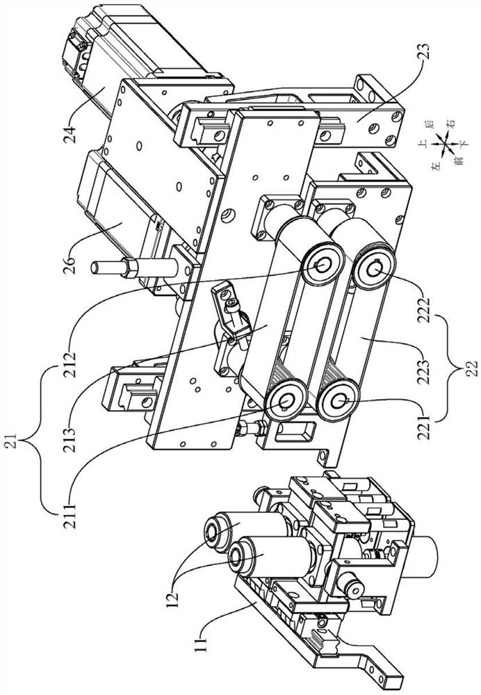
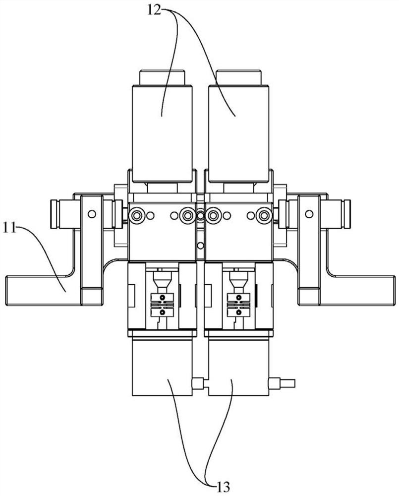
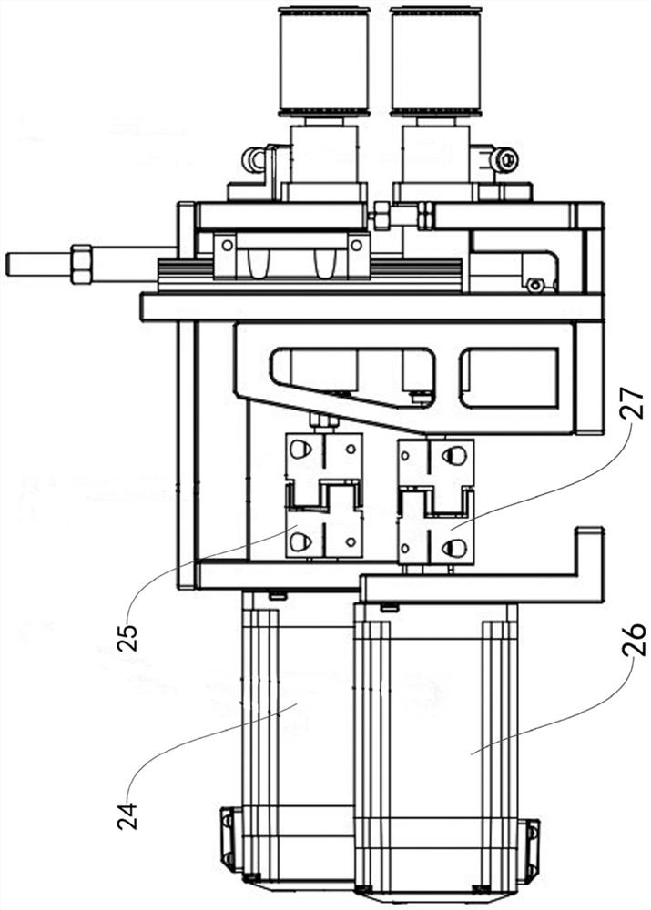
[0026] like figure 1 As shown, the pipe length counting device according to the embodiment of the present invention includes a frame, a length counting assembly 1, a conveying assembly 2 and a controller, the length counting assembly 1 is installed on the frame, and the length counting assembly 1 is used for measuring The displacement signal of the pipe is converted into an electrical signal. The conveying assembly 2 is installed on the frame. The conveying assembly 2 includes an upper roller set 21 and a lower roller set 22. The upper roller set 21 and the lower roller set 22 are arranged at intervals in the up and down direction. The upper roller set 21 and the lower roller set 22 are used to clamp the measured pipe, and under the cooperation of the upper roller set 21 and the lower roller set 22, the north side pipe is transported to the length gauge assembly 1; the controller and The metering component 1 is connected, and the controller receives and processes the electrical signal input by the metering component 1, and stores the processed data; the measured pipe is from figure 1 The right side enters the conveying assembly 2 first, and is transported to figure 1 The length measuring component 1 on the left, the measured pipe generates an electrical signal after passing through the length measuring component 1, and the generated electrical signal is input to the controller, and the controller measures the length of the measured pipe in real time during transportation through weighted average.
[0027] According to the pipe length measuring device of the embodiment of the present invention, the device adopts the arrangement mode of the conveying assembly 2 in front and the length measuring assembly 1 in the rear, which reduces the loss of length counting accuracy caused by the sliding friction between the material and the roller. Influence, and for some materials with strong ductility in the length direction, it also avoids the effect of increasing the length of the material after being squeezed by two rollers, and solves the problem of inaccurate length calculation of flexible materials.
[0028] like figure 1 and figure 2 As shown, in some embodiments, the length gauge assembly 1 includes a first mount 11, a first roller 12 and an encoder 13, the first mount 11 is arranged on the frame, and the first roller The wheel 12 is rotatably mounted on the first mounting seat 11, and there are two first rollers 12, the central axes of the two first rollers 12 are parallel to each other, and the two first rollers 12 are arranged along the pipe under test. There are two encoders 13 at intervals in the radial direction, and the two encoders 13 are arranged in one-to-one correspondence with the two first rollers 12. The encoder 13 is connected to one end of the first roller 12, and the encoder 13 will The number of turns of the first roll shaft rotation is converted into an electrical signal, and the two encoders 13 are electrically connected to the controller respectively;
[0029] The specific installation method of the first roller wheel 12 and the encoder 13 is as follows: the first roller shaft is rotatably connected with the first roller shaft, the central axis of the first roller shaft is arranged along the vertical direction, and the first roller shaft is arranged along the vertical direction. Going through the first mounting base 11, the first roller 12 is sleeved on the upper end of the first roller shaft, and the encoder 13 is installed on the lower end of the first roller shaft;
[0030] The detection process of the pipe under test: after the pipe under test enters the length meter assembly 1, the pipe under test passes between the two first rollers 12 and drives the two first rollers 12 to rotate relative to each other, and the first roller 12 will The stroke of the pipe under test is transmitted to the corresponding encoder 13 through the first mounting base 11, and then the controller receives the pulse signals from the two encoders 13, and performs weighted average processing to measure the length of the pipe under test in real time. .
[0031] like figure 1 and image 3 As shown, in some embodiments, the conveying assembly 2 further includes a second mounting base 23, the second mounting base 23 is arranged on the frame, and the upper roller set 21 and the lower roller set 22 can rotate It is installed on the second installation seat 23 , and the pipe to be tested passes between the upper roller set 21 and the lower roller set 22 .
[0032] like figure 1 and image 3 As shown, in some embodiments, the upper roller set 21 includes a second roller 211, a third roller 212 and a first conveyor belt 213, and the second roller 211 is rotatably arranged on the second mounting seat 23, the third roller 212 is rotatably arranged on the second mount 23, the central axes of the second roller 211 and the third roller 212 are parallel to each other, the second roller 211 and the third roller 212 Arranged at intervals along the length direction of the measured pipe, the second roller 211 is closer to the length meter assembly 1 than the third roller 212, and the first conveyor belt 213 is arranged around the second roller 211 and the third roller 212;
[0033] The specific installation method of the second roller 211 and the third roller 212: the second mounting seat 23 is rotatably connected with the second roller shaft, the central axis of the second roller shaft is arranged along the front and rear direction, and the second roller 211 covers Fixed on the front end of the second roller shaft, the second mounting base 23 is rotatably connected with the third roller shaft, the central axis of the third roller shaft is arranged along the front and back direction, and the third roller wheel 212 is sleeved on the third roller shaft. front end.
[0034] like image 3 As shown, in some embodiments, the conveying assembly 2 further includes a first motor 24 and a first coupling 25, the first motor 24 is arranged on the frame, and the first motor 24 is located on the second installation Behind the seat 23, the output shaft of the first motor 24 is connected to the rear end of the third roller shaft through the first coupling 25, so that the first motor 24 drives the third roller 212 to rotate, thereby driving the first conveyor belt 213 runs.
[0035] like image 3As shown, in some embodiments, the lower roller set 22 includes a fourth roller 221, a fifth roller 222 and a second conveyor belt 223, and the fourth roller 221 is rotatably arranged on the second mounting seat 23, the position of the fourth roller 221 corresponds to the position of the second roller 211 up and down, and the fifth roller 222 is rotatably arranged on the second mount 23, and the position of the fifth roller 222 is the same as that of the third roller 222. The positions of the rollers 212 correspond up and down, the central axes of the fourth roller 221 and the fifth roller 222 are parallel to each other, the fourth roller 221 and the fifth roller 222 are arranged at intervals along the length direction of the pipe to be tested, and the second The conveyor belt 223 is arranged around the fourth roller 221 and the fifth roller 222;
[0036] The specific installation method of the fourth roller 221 and the fifth roller 222: the second mounting seat 23 is rotatably connected with the fourth roller shaft, the central axis of the fourth roller shaft is arranged along the front and rear direction, and the fourth roller 221 sets Fixed on the front end of the fourth roller shaft, the second mounting base 23 is rotatably connected with the fifth roller shaft, the central axis of the fifth roller shaft is arranged along the front and back direction, and the fifth roller wheel 222 is sleeved and fixed on the fifth roller shaft. front end.
[0037] like image 3 As shown, in some embodiments, the conveying assembly 2 further includes a second motor 26 and a second coupling 27, the second motor 26 is arranged on the frame, and the second motor 26 is located on the second installation Behind the seat 23, the output shaft of the second motor 26 is connected to the rear end of the fourth roller shaft through the second coupling 27, so that the second motor 26 drives the fourth roller 221 to rotate, thereby driving the second conveyor belt 223 runs.
[0038] The delivery process of the tested pipe fittings: such as Figure 4 As shown, the measured pipe enters the conveying assembly 2 from the right side, the first motor 24 drives the first conveying belt 213 to rotate clockwise from the front to the rear, and the second motor 26 drives the second conveying belt 223 to rotate from the front to the rear Turning counterclockwise in the direction of viewing, under the action of the first conveyor belt 213 and the second conveyor belt 223, the pipe to be measured is clamped and transported to the length gauge assembly 1 from right to left.
[0039] In some embodiments, the controller is a PLC controller.
[0040] The following describes pipe length measuring devices according to some specific examples of the present invention with reference to the accompanying drawings.
[0041] like figure 1 As shown, the pipe length counting device according to the embodiment of the present invention includes a frame, a length counting assembly 1, a delivery assembly 2 and a controller, the length counting assembly 1 is installed on the frame, the delivery assembly 2 is installed on the frame, and the delivery assembly 2 is located on the right side of the length counting assembly 1; the conveying assembly 2 includes an upper roller set 21 and a lower roller set 22, the upper roller set 21 and the lower roller set 22 are arranged at intervals in the up and down direction, and the upper roller set 21 is located at the bottom of the lower roller set 22 Above; the controller is connected to the length meter component 1, and the controller is a PLC controller.
[0042] like figure 1 and figure 2 As shown, the length gauge assembly 1 includes a first mount 11, a first roller 12 and an encoder 13, the first mount 11 is arranged on the frame, and the first mount 11 is rotatably connected with two first roller shafts , the central axis of the first roller shaft is vertically arranged, the two first roller shafts are arranged at intervals along the radial direction of the pipe to be tested, and the upper and lower ends of the two first roller shafts are flush, and the first roller 12 has two And corresponding to the two first roller shafts one by one, the first roller wheel 12 is sleeved on the upper end of the corresponding first roller shaft, and there are two encoders 13 corresponding to the two first roller shafts one by one. 13 is installed on the lower end of the corresponding first roller shaft, and the two encoders 13 are respectively electrically connected to the controller.
[0043] like figure 1 As shown, the conveying assembly 2 also includes a second mounting base 23, the second mounting base 23 is arranged on the frame, the second roller shaft is rotatably connected to the second mounting base 23, and the third roller shaft is rotatably connected to the second mounting base 23. The central axes of the rollers, the second rollers and the third rollers are arranged along the front-to-back direction, and the second rollers and the third rollers are arranged at intervals along the length direction of the pipe to be tested; the upper roller group 21 includes a second roller 211 , the third roller 212 and the first conveyor belt 213, the second roller 211 is sleeved on the front end of the second roller shaft, the third roller 212 is sleeved on the front end of the third roller shaft, and the first conveyor belt 213 surrounds the first The second roller 211 and the third roller 212 are set; the second mounting seat 23 is rotatably connected with a fourth roller shaft, and the position of the fourth roller shaft corresponds to the position of the second roller shaft up and down, and the second mounting seat 23 is rotatably connected There is a fifth roller, the position of the fifth roller corresponds to the position of the third roller up and down, the central axes of the fourth roller and the fifth roller are set along the front and rear directions, and the fourth roller and the fifth roller are arranged along the The length direction of the measured pipe is arranged at intervals; the lower roller group 22 includes a fourth roller 221, a fifth roller 222 and a second conveyor belt 223, the fourth roller 221 is sleeved on the front end of the fourth roller shaft, and the fifth roller The wheel 222 is sleeved on the front end of the fifth roller, the second conveyor belt 223 is arranged around the fourth roller 221 and the fifth roller 222 , and the first conveyor belt 213 and the second conveyor belt 223 are parallel to each other.
[0044] like image 3 As shown, the conveying assembly 2 also includes a first motor 24 and a first coupling 25, the first motor 24 is arranged on the frame, the first motor 24 is located at the rear of the second mount 23, and the output shaft of the first motor 24 Link to each other with the rear end of the 3rd roller shaft by the first coupling 25; Conveyor assembly 2 also comprises the second motor 26 and the second coupling 27, and the second motor 26 is arranged on the frame, and the second motor 26 is positioned at the first At the rear of the second mounting seat 23, the output shaft of the second motor 26 is connected to the rear end of the fourth roller shaft through the second coupling 27.
[0045] The overall detection process of the pipe length measuring device will be described below.
[0046] Insert the measured pipe between the first conveyor belt 213 and the second conveyor belt 223, then start the first motor 24 and the second motor 26, the first motor 24 drives the third roller to rotate, and the third roller drives the third The roller 212 rotates, the third roller 212 drives the first conveyor belt 213 to run, the second motor 26 drives the fourth roller shaft to rotate, the fourth roller shaft drives the fourth roller 221 to rotate, and the fourth roller 221 drives the second conveyor belt The belt 223 runs, the first conveyor belt 213 and the second conveyor belt 223 rotate relative to each other, the pipe to be tested is transported to the gauge assembly 1 through the first conveyor 213 and the second conveyor 223, and the pipe to be tested penetrates two Between the first rollers 12, the pipe under test drives the two first rollers 12 to rotate relative to each other, the first roller 12 drives the first roller to rotate, and the encoder 13 converts the number of rotations of the first roller into electrical signals And transmit it to the controller, the controller processes the signal and stores the data to realize the real-time measurement of the measured pipe fittings.
[0047] In describing the present invention, it should be understood that the terms "center", "longitudinal", "transverse", "length", "width", "thickness", "upper", "lower", "front", " Back", "Left", "Right", "Vertical", "Horizontal", "Top", "Bottom", "Inner", "Outer", "Clockwise", "Counterclockwise", "Axial", The orientation or positional relationship indicated by "radial", "circumferential", etc. is based on the orientation or positional relationship shown in the drawings, and is only for the convenience of describing the present invention and simplifying the description, rather than indicating or implying the referred device or element Must be in a particular orientation, be constructed in a particular orientation, and operate in a particular orientation, and therefore should not be construed as limiting the invention.
[0048] In addition, the terms "first" and "second" are used for descriptive purposes only, and cannot be interpreted as indicating or implying relative importance or implicitly specifying the quantity of indicated technical features. Thus, the features defined as "first" and "second" may explicitly or implicitly include at least one of these features. In the description of the present invention, "plurality" means at least two, such as two, three, etc., unless otherwise specifically defined.
[0049] In the present invention, unless otherwise clearly specified and limited, terms such as "installation", "connection", "connection" and "fixation" should be understood in a broad sense, for example, it can be a fixed connection or a detachable connection , or integrated; can be mechanically connected, can also be electrically connected or can communicate with each other; can be directly connected, can also be indirectly connected through an intermediary, can be the internal communication of two components or the interaction relationship between two components, Unless expressly defined otherwise. Those of ordinary skill in the art can understand the specific meanings of the above terms in the present invention according to specific situations.
[0050] In the present invention, unless otherwise clearly specified and limited, the first feature may be in direct contact with the first feature or the first and second feature may be in direct contact with the second feature through an intermediary. touch. Moreover, "above", "above" and "above" the first feature on the second feature may mean that the first feature is directly above or obliquely above the second feature, or simply means that the first feature is higher in level than the second feature. "Below", "beneath" and "beneath" the first feature may mean that the first feature is directly below or obliquely below the second feature, or simply means that the first feature is less horizontally than the second feature.
[0051] As used herein, the terms "one embodiment," "some embodiments," "example," "specific examples," or "some examples" mean specific features, structures, materials, or features described in connection with the embodiment or example. A feature is included in at least one embodiment or example of the invention. In this specification, the schematic representations of the above terms are not necessarily directed to the same embodiment or example. Furthermore, the described specific features, structures, materials or characteristics may be combined in any suitable manner in any one or more embodiments or examples. In addition, those skilled in the art can combine and combine different embodiments or examples and features of different embodiments or examples described in this specification without conflicting with each other.
[0052] Although the embodiments of the present invention have been shown and described above, it can be understood that the above embodiments are exemplary and should not be construed as limiting the present invention, and those skilled in the art can make the above-mentioned The embodiments are subject to changes, modifications, substitutions and variations.

PUM

no PUM

Description & Claims & Application Information

We can also present the details of the Description, Claims and Application information to help users get a comprehensive understanding of the technical details of the patent, such as background art, summary of invention, brief description of drawings, description of embodiments, and other original content. On the other hand, users can also determine the specific scope of protection of the technology through the list of claims; as well as understand the changes in the life cycle of the technology with the presentation of the patent timeline. Login to view more.
Why Eureka
Try Eureka