A comprehensive sediment treatment device for hydraulic engineering
A technology for water conservancy projects and treatment devices, which is applied in solid separation, chemical instruments and methods, grids, etc., can solve the problems of decreased sediment filtration efficiency and easy blockage of the filter screen, and achieves prevention of blockage, simple power source, and guaranteed filtration efficiency. Effect
- Summary
- Abstract
- Description
- Claims
- Application Information
AI Technical Summary
Problems solved by technology
Method used
Image
Examples
Embodiment 1
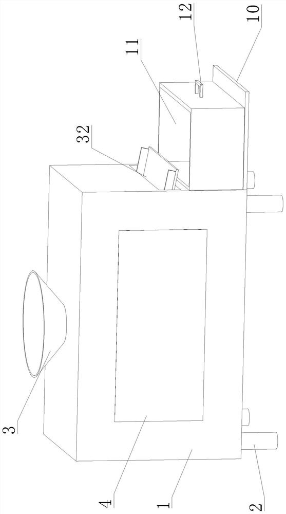
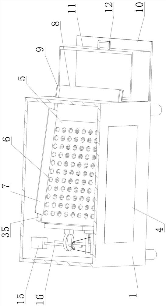
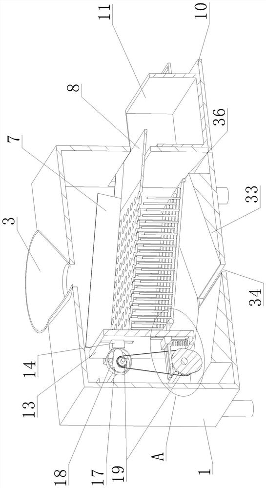
[0021] like Figure 1-4 As shown, a comprehensive sediment treatment device for hydraulic engineering proposed by the present invention includes a box body 1, a filter plate 5, a vertical plate 13, a motor 15, a rotating shaft a16 and a slider b22;
[0022] The bottom of the box body 1 is provided with multiple sets of support legs 2 , the top and bottom of the box body 1 are respectively provided with a feeding cone 3 and a discharge chute 34 , the front side of the box body 1 is provided with a transparent observation window 4 , and the inner side of the bottom of the box body 1 is provided with two sets of guides. The material table 33, the two groups of material guide tables 33 are symmetrical with respect to the discharge chute 34, and the upper end surfaces of the two groups of material guide tables 33 are provided with material guide inclined surfaces; The sliding plates 35 are all inclined on the side inner walls, and the inclination angle of the sliding plates 35 is e...
Embodiment 2
[0025] The present invention proposes a comprehensive sediment treatment device for hydraulic engineering. Compared with the first embodiment, the vibration component includes a slider a14, a cam a17 and a ring 18; The end face of the filter plate 5; the ring 18 is vertically arranged on the end face of the slider a14 facing away from the vertical plate 13; the cam a17 is arranged on the rotating shaft a16, the axis of the cam a17 does not coincide with the axis of the rotating shaft a16, and the length of the cam a17 The edges are all in contact with the inner wall of the ring 18 .
[0026] In this embodiment, the cam a17 rotates in the ring 18, driving the ring 18 to move, and the ring 18 drives the vertical plate 13 to move through the slider a14, thereby driving the filter plate 5 to move back and forth, which has the effect of vibration filtering.
Embodiment 3
[0028] The present invention proposes a comprehensive sediment treatment device for hydraulic engineering. Compared with the first embodiment, the lifting assembly includes a sprocket 19, a chain 20, a supporting plate b27, a spring 28, a supporting plate a29, a cam b31 and a rotating shaft b37; The shaft b37 is rotatably arranged on the front and rear inner walls of the box body 1, the rotating shaft b37 is arranged vertically and horizontally, and the rotating shaft b37 is located below the rotating shaft a16; On the upper side, the two groups of sprockets 19 are connected by chain 20 transmission; the support plate a29 is horizontally arranged on the end face of the slider b22 facing away from the vertical plate 13, and the support plate a29 is provided with a strip groove b30 for the chain 20 to pass through; The cam b31 is arranged on the rotating shaft b37, the cam b31 is located below the support plate a29 and is in contact with the bottom of the support plate a29; the s...
PUM
 Abstract
Description
Claims
Application Information
 - R&D
- Intellectual Property
- Life Sciences
- Materials
- Tech Scout
- Unparalleled Data Quality
- Higher Quality Content
- 60% Fewer Hallucinations
Browse by: Latest US Patents, China's latest patents, Technical Efficacy Thesaurus, Application Domain, Technology Topic, Popular Technical Reports.
© 2025 PatSnap. All rights reserved.Legal|Privacy policy|Modern Slavery Act Transparency Statement|Sitemap|About US| Contact US: help@patsnap.com


