Al technical title is built by PatSnap Al team. It summarizes the technical point description of the patent document.
A charging system and circuit technology, applied in electric vehicle charging technology, charging stations, battery circuit devices, etc., can solve problems such as environmental tolerance to be improved
Pending Publication Date: 2022-01-25
山东万群信息技术有限公司
View PDF0 Cites 0 Cited by
Summary
Abstract
Description
Claims
Application Information
AI Technical Summary
This helps you quickly interpret patents by identifying the three key elements:
Problems solved by technology
Method used
Benefits of technology
Problems solved by technology
Although considerable progress has been made in charging technology, such charging stations still need to be improved in terms of circuit control, resource allocation, and user-oriented functions; moreover, as charged equipment exposed to the external environment for a long time , and its environmental tolerance also needs to be improved
Method used
Image
Click on the blue label to locate the original text in one second.
Reading with bidirectional positioning of images and text.
Examples
Embodiment 1
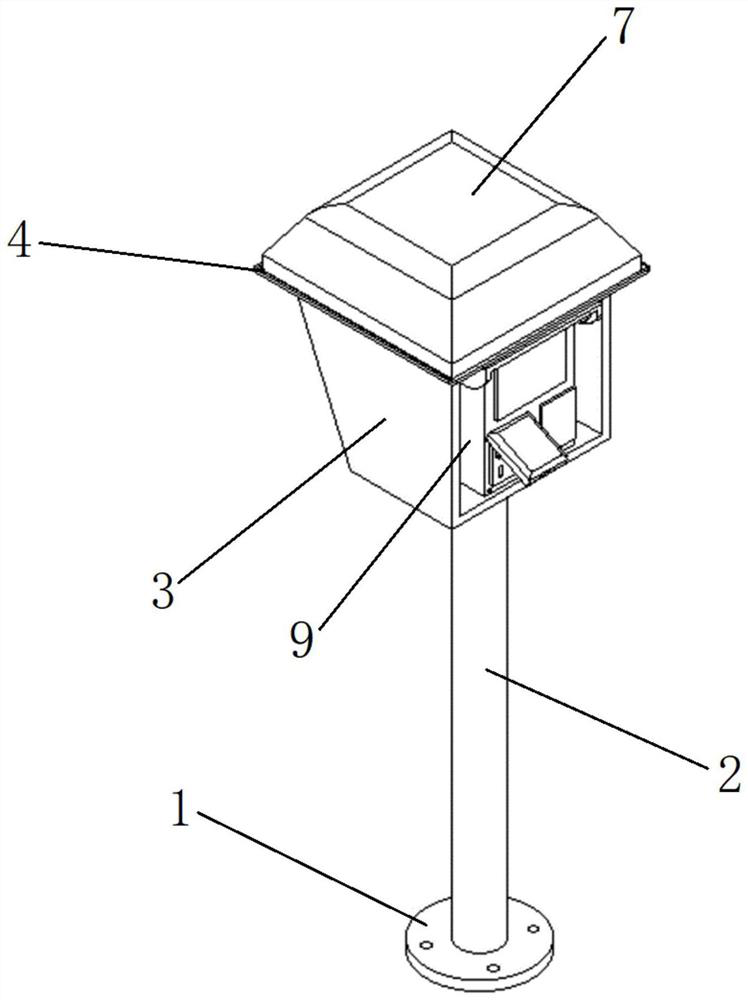
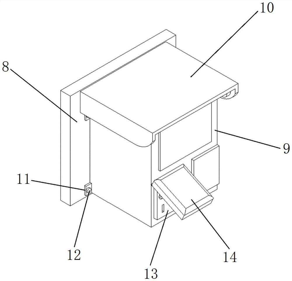
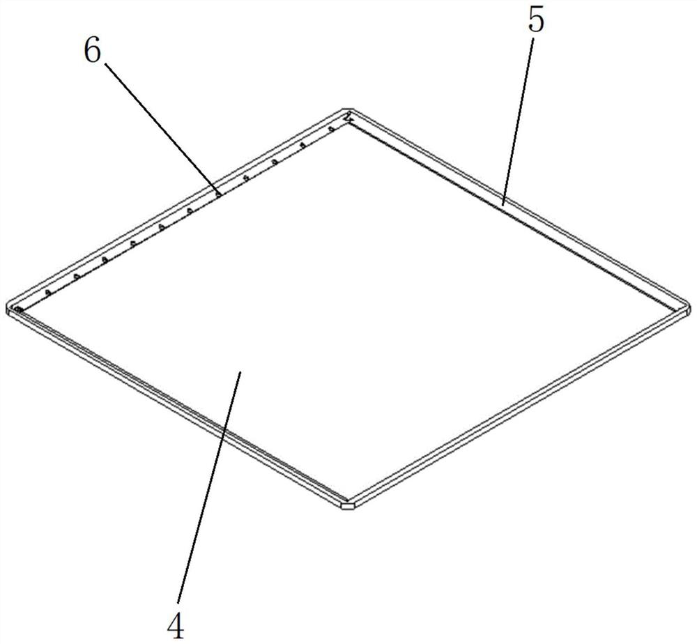
[0026] Shared electricity charging system, such as Figure 1~3 As shown, it includes base 1, pillar 2, box body 3, water collecting pan 4, annular groove 5, drain hole 6, top cover 7, back plate 8, box body 9, cover 10, wing plate 11, fixing bolts 12 , a socket 13, a protective case 14, wherein a base 1 is welded at the bottom of the pillar 2, the base 1 is fixed on the ground through ground nails or embedded parts, there is a box body 3 at the top of the pillar 2, and the box body 3 The top end is fixedly connected with a water collecting pan 4, an annular groove 5 is provided on the outer edge of the water collecting pan 4, a drainage hole 6 is opened on the annular groove 5, a top cover 7 is provided on the water collecting pan 4, and the outer edge of the water collecting pan 4 The edge is larger than the outer edge of the top cover 7 and larger than the outer edge of the box body 3. There is a back plate 8 inside the box body 3, a protective cover 10 at the top of the box...
Embodiment 2
[0029] Shared electricity charging system, such as Figure 1~4 As shown, it includes base 1, pillar 2, box body 3, water collecting pan 4, annular groove 5, drain hole 6, top cover 7, back plate 8, box body 9, cover 10, wing plate 11, fixing bolts 12 , a socket 13, a protective case 14, wherein a base 1 is welded at the bottom of the pillar 2, the base 1 is fixed on the ground through ground nails or embedded parts, there is a box body 3 at the top of the pillar 2, and the box body 3 The top end is fixedly connected with a water collecting pan 4, an annular groove 5 is provided on the outer edge of the water collecting pan 4, a drainage hole 6 is opened on the annular groove 5, a top cover 7 is provided on the water collecting pan 4, and the outer edge of the water collecting pan 4 The edge is larger than the outer edge of the top cover 7 and larger than the outer edge of the box body 3. There is a back plate 8 inside the box body 3, a protective cover 10 at the top of the box...
PUM
Abstract
The invention provides a shared electricity charging system. According to the technical scheme, on one hand, the control scheme of the circuit is improved, and on the other hand, a brand-new waterproof structure is designed. In the aspect of the waterproof structure, firstly, an electrified part of equipment is kept at a certain height through the supporting columns, so that the problem of rainwater soaking is solved; on the basis, a water collecting tray with an annular groove is additionally arranged at the top of the equipment, so that rainwater can be shielded and guided; and meanwhile, a protective shell is additionally arranged at the front end of the socket of the equipment, so that the problems of rainwater infiltration, external force damage and the like are relieved to a certain extent. In the aspect of circuit control, the main control unit is used for communicating with an operation and maintenance platform and a user APP, meanwhile, the main control unit is used for controlling the circuit on-off mechanism, and the circuit on-off mechanism achieves power supply control over the 220v power socket, the mobile phone charging socket and the electric vehicle charging socket. According to the invention, outdoor charging and power utilization are more convenient, and higher environmental tolerance is achieved.
Description
technical field [0001] The invention relates to the technical field of power supply equipment, in particular to a charging system for sharing electricity. Background technique [0002] With the development of smart phones, electric vehicles and other products, consumers have increasingly extensive charging needs for electrical equipment. How to charge anytime and anywhere has always been a technical problem to be solved. This not only involves the construction of infrastructure, but also affects the New requirements have been put forward in terms of charging speed, charging management and settlement methods. [0003] In the prior art, charging stations for mobile phones and electric vehicles have gradually begun to be built. Such facilities, like gas stations for automobiles, are set up in shops along the street, in street communities, next to newsstands, storage sheds, betting points, etc. Among them, the electric vehicle charging station adopts pulse, which has a good des...
Claims
Application Information
Patent Timeline
Application Date:The date an application was filed.
Publication Date:The date a patent or application was officially published.
First Publication Date:The earliest publication date of a patent with the same application number.
Issue Date:Publication date of the patent grant document.
PCT Entry Date:The Entry date of PCT National Phase.
Estimated Expiry Date:The statutory expiry date of a patent right according to the Patent Law, and it is the longest term of protection that the patent right can achieve without the termination of the patent right due to other reasons(Term extension factor has been taken into account ).
Invalid Date:Actual expiry date is based on effective date or publication date of legal transaction data of invalid patent.