Roller type toggle clip device of steel door
A roller and steel technology, which is applied in the field of roller-type clamping devices, can solve the problems of laborious closing of the hatch cover, achieve the effect of simple locking structure, prolong the moving buffer of the pulley, and improve the efficiency
- Summary
- Abstract
- Description
- Claims
- Application Information
AI Technical Summary
Problems solved by technology
Method used
Image

Examples
Embodiment 1
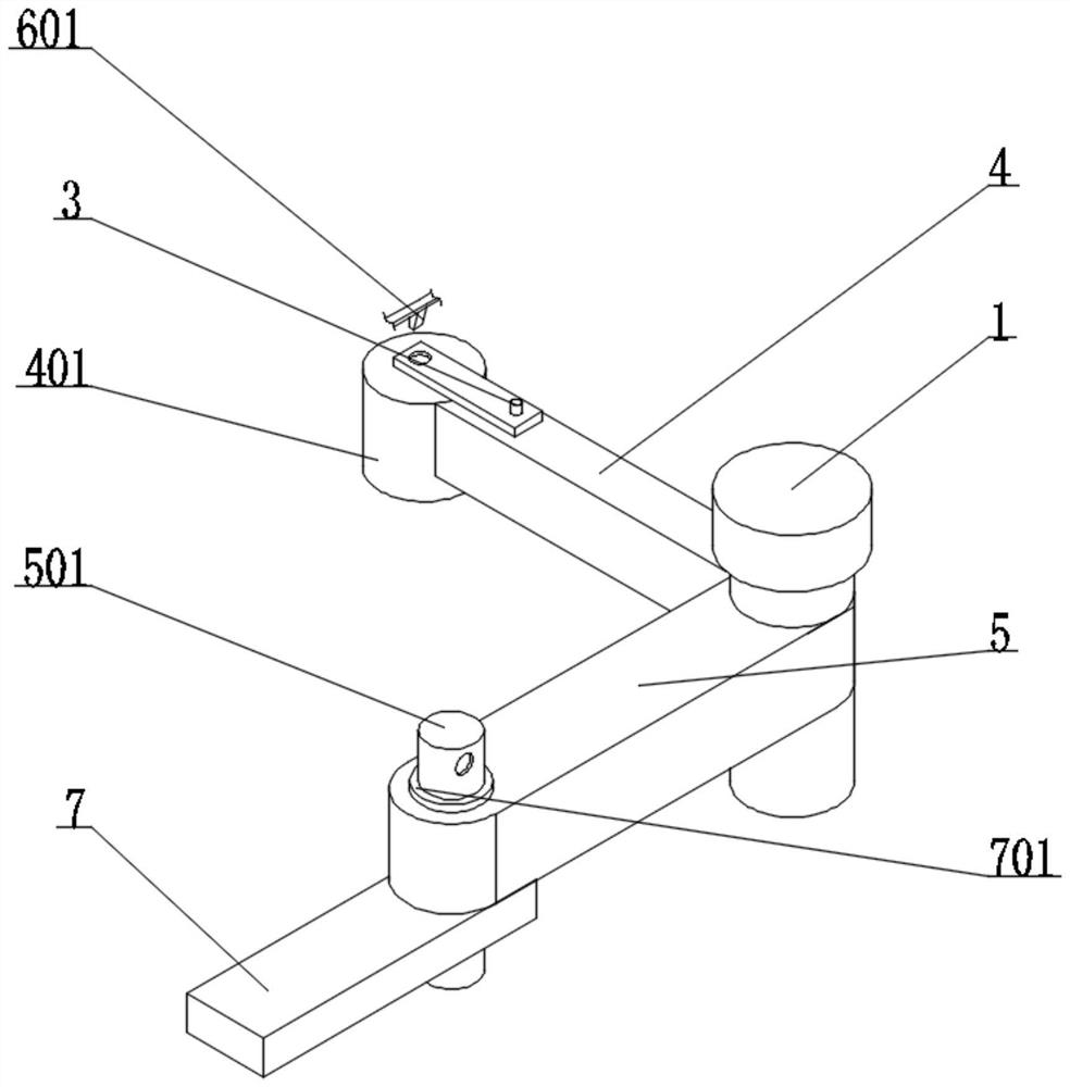
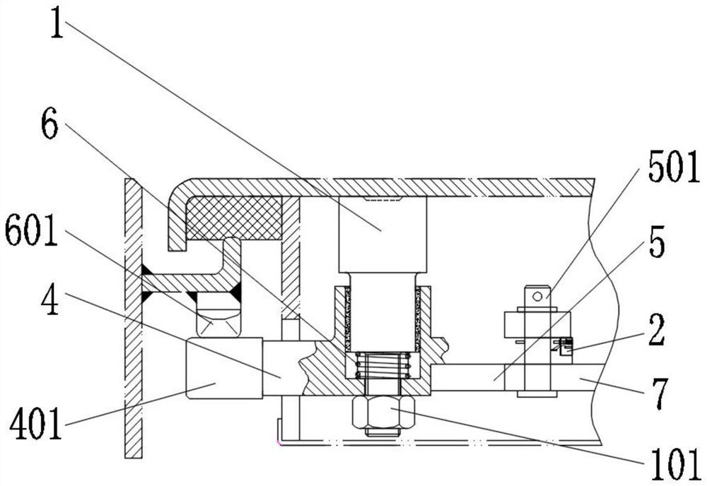
[0026] Example 1: See figure 1 and figure 2 , a roller-type clamping device for a steel door, comprising a buckle seat 1, a protective case 2 and a first pillar 3, the function of the buckle seat 1 is to provide support for the device, and the function of the protective case 2 is to provide support for the first spring 204 Protection, the function of the first pillar 3 is to provide mobile support for the pulley 401, the outer wall of the buckle seat 1 is equipped with the first pole 4, the role of the first pole 4 is to provide support for the pulley 401, the outer wall of the first pole 4 A first pillar 3 is installed, and a second pole 5 is installed on the outer wall of the buckle seat 1. The function of the second pole 5 is to provide support for the buckle seat 1. A protective shell 2 is installed on the inner wall of the second pole 5, and the buckle seat The inner wall of 1 is equipped with a second spring 6, the function of the second spring 6 is to provide conditio...
Embodiment 2
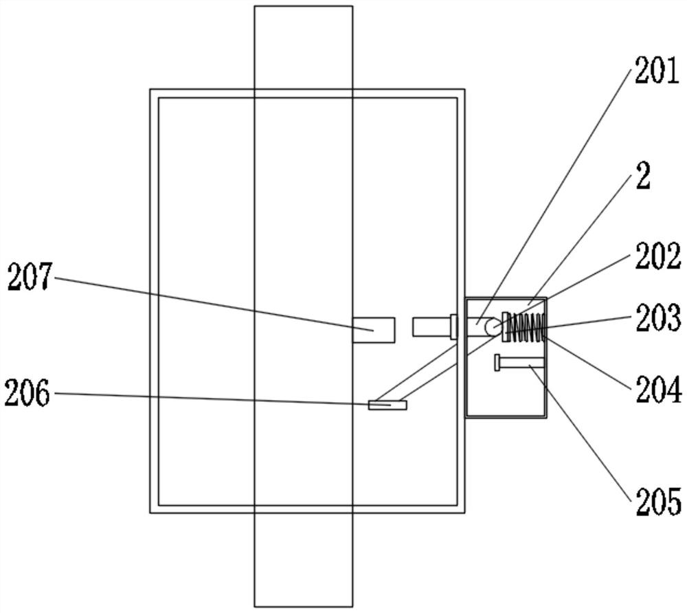
[0027] Example 2: See image 3 A first spring 204 is installed on the inner wall of the protective case 2, a first support block 203 is installed on one end of the first spring 204, a first bearing 202 is installed on the outer wall of the first support block 203, and a first bearing 202 is installed on the outer wall of the first bearing 202. One connecting rod 201, one end of the first connecting rod 201 is equipped with a pressure block 206, the inner wall of the second pole 5 is equipped with a sleeve, and one end of the first connecting rod 201 extends to one end of the sleeve, the inner wall of the protective shell 2 A support column 205 is installed, and the outer wall of the positioning column 501 is equipped with a push head 207. The function of the sleeve is to provide fixation for the first connecting rod 201, and the function of the supporting column 205 is to provide support for the first connecting rod 201, and the positioning column 501 moves The push head 207 i...
Embodiment 3
[0028] Example 3: See Figure 4 , the outer wall of the first pillar 3 is equipped with a third spring 305, one end of the third spring 305 is equipped with a second support block 301, the outer wall of the second support block 301 is equipped with a second support 306, and the outer wall of the first support 3 is installed with The third support block 303, the outer wall of the third support block 303 is equipped with a second bearing 304, the outer wall of the second bearing 304 is equipped with a second connecting rod, and one end of the second connecting rod is connected with the inner wall of the first pole 4, The outer wall of the connecting rod is equipped with a third bearing 302, the movement of the pulley 401 drives the movement of the first pillar 3, the movement of the first pillar 3 drives the movement of the third support block 303, the movement of the third support block 303 drives the movement of the second bearing 304, and the movement of the second bearing Th...
PUM
 Abstract
Description
Claims
Application Information
 - R&D
- Intellectual Property
- Life Sciences
- Materials
- Tech Scout
- Unparalleled Data Quality
- Higher Quality Content
- 60% Fewer Hallucinations
Browse by: Latest US Patents, China's latest patents, Technical Efficacy Thesaurus, Application Domain, Technology Topic, Popular Technical Reports.
© 2025 PatSnap. All rights reserved.Legal|Privacy policy|Modern Slavery Act Transparency Statement|Sitemap|About US| Contact US: help@patsnap.com