
Sensor assembly

A sensor component and sensor technology, applied in the direction of central heating sensors, instruments, cooking utensils, etc., can solve the problems of insufficient measurement, hindering normal functions, etc.

Pending Publication Date: 2022-02-01
BREVILLE HLDG PTY LTD
View PDF0 Cites 0 Cited by
  • Summary
  • Abstract
  • Description
  • Claims
  • Application Information

AI Technical Summary

Problems solved by technology

Disadvantageously, scale can deposit on critical parts of sensors used in appliances (such as negative temperature coefficient "NTC" type thermistors), preventing proper function and resulting in insufficient measurements

Method used


Image

  • Sensor assembly
  • Sensor assembly
  • Sensor assembly

Examples


Embodiment Construction

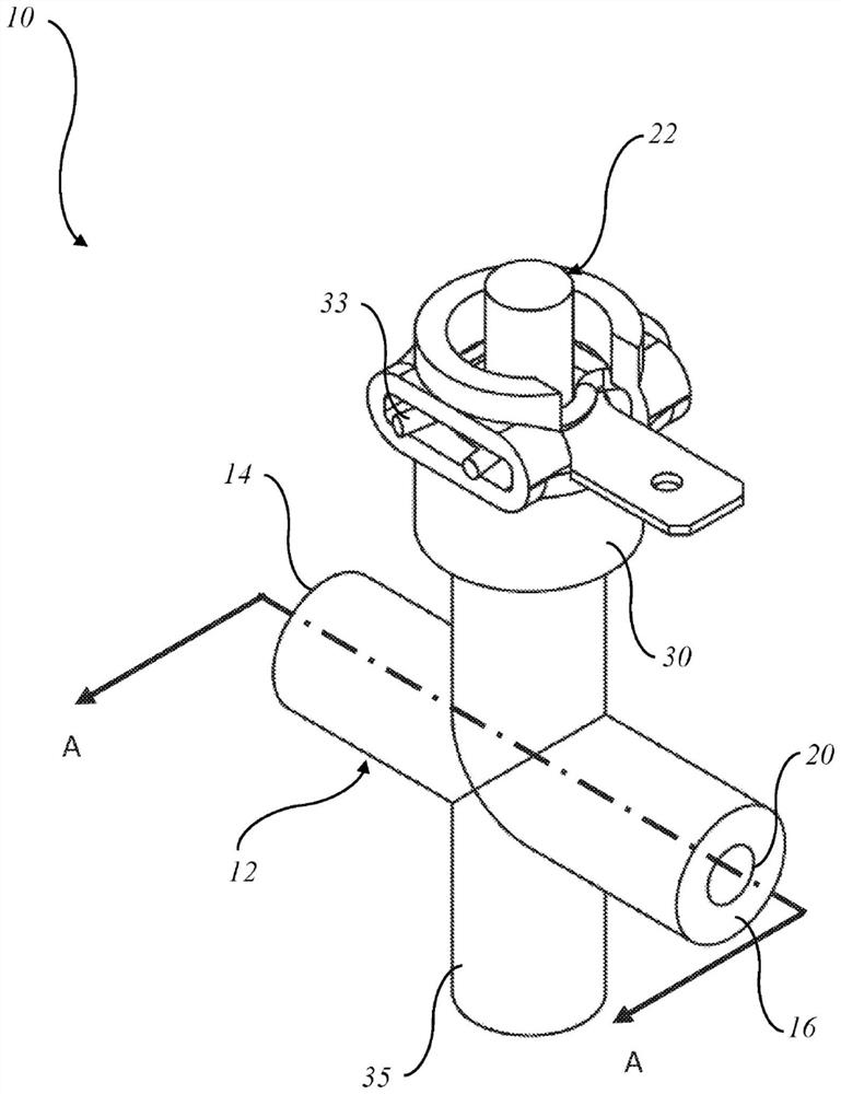
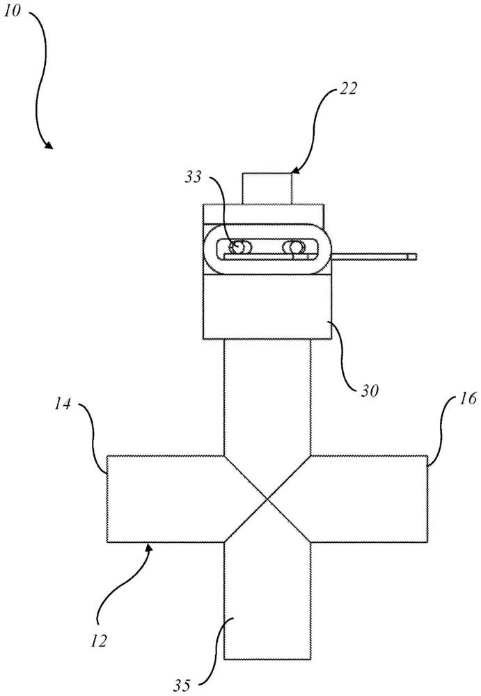
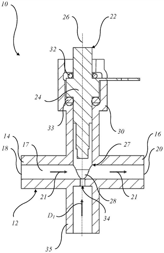
[0040] First refer to the attached Figure 1 to Figure 3 , schematically depicts a sensor assembly 10 for an appliance 100 , 200 . The appliance 100, 200 is configured to heat a liquid, such as water, to make a beverage, such as coffee.

[0041] The assembly 10 includes a conduit in the form of a tube 12 having longitudinally opposed first and second ends 14 and 16 . like image 3 As shown, tube 12 has an inlet 18 adjacent first end 14 and an outlet 20 adjacent second end 16 . Tube 12 has a longitudinal sidewall 17 extending between an inlet 18 and an outlet 20 to provide a liquid flow path 21 extending linearly between first end 14 and second end 16 .

[0042] The assembly 10 also includes a sensor 22 for measuring line parameters (eg, temperature, pressure, flow, clarity, etc.) of the liquid flowing along the path 21 . In a preferred embodiment, the sensor 22 is an NTC type sensor configured to measure the temperature of the liquid.

[0043] The sensor 22 has a body 24 ...


PUM


Abstract

An appliance (100, 200) for heating a liquid to make a beverage, the appliance (1) including: a sensor assembly (10) including: a duct (12) having an inlet (18) and an outlet (20), the duct (12) defining a liquid flow path (21) between the inlet (18) and the outlet (20) for the liquid; a sensor (22) having an operative end portion (28) in the flow path (21) for measuring line parameters of the liquid in the flow path (21); and a nozzle (34) to receive water under pressure and direct a water jet transverse to the flow path (21) and towards the operative end portion (28) of the sensor (22) to at least aid in cleaning the operative end portion (28) of the sensor (22).

Description

technical field [0001] The present invention relates to sensor assemblies, and in particular but not exclusively to sensor assemblies for use in appliances for heating liquids. Background technique [0002] Known appliances for heating liquids, such as kettles, coffee makers, tea makers, etc., heat water, for example for use in preparing beverages. Repeated heating of water in appliances, especially hard water, often leads to limescale formation. Disadvantageously, scale can deposit on critical parts of sensors used in appliances (such as negative temperature coefficient "NTC" type thermistors), preventing proper function and resulting in insufficient measurements. As more water is heated, more scale will form which may continue to deposit on the sensor. [0003] purpose of invention [0004] It is an object of the present invention to substantially overcome or at least ameliorate one or more of the aforementioned disadvantages. Contents of the invention [0005] In a...

Claims


Application Information

Patent Timeline
Patent Type & Authority Applications(China)
IPC IPC(8): A47J31/60A47J31/56A47J31/54B67D1/02B08B3/02
CPCB08B3/02A47J31/56A47J31/60G01K13/026B05B1/3006G01K7/22A47J2202/00F24H15/219F24H15/288F24H15/14A47J27/21066F24D2220/04A47J31/461A47J31/468
Inventor T-K·贡A·M·D·梁A·托法伊利C·普萨罗洛格斯S·J·麦克林
Owner BREVILLE HLDG PTY LTD
Learn More