
Lateral punching reset structure

A reset structure and lateral punching technology, applied in the field of punching die, can solve the problems of low work efficiency, unstable punch reset, insufficient reset spring force, etc., and achieve the effect of improving work efficiency and stable and fast punch reset.

Pending Publication Date: 2022-02-08
SUZHOU UIGREEN MICRO & NANO TECH CO LTD
View PDF0 Cites 0 Cited by
  • Summary
  • Abstract
  • Description
  • Claims
  • Application Information

AI Technical Summary

Problems solved by technology

[0002] At present, the known lateral punching reset method is to install the spring between the punch holder and the punch guide plate. Due to the narrow space, the diameter of the spring is too small and the length is too short, so that the force of the reset spring is not enough and the punching Unstable head reset, low work efficiency

Method used


Image

  • Lateral punching reset structure
  • Lateral punching reset structure
  • Lateral punching reset structure

Examples


Embodiment Construction

[0018] The following will clearly and completely describe the technical solutions in the embodiments of the present invention with reference to the accompanying drawings in the embodiments of the present invention. Obviously, the described embodiments are only some, not all, embodiments of the present invention. Based on the embodiments of the present invention, all other embodiments obtained by persons of ordinary skill in the art without making creative efforts belong to the protection scope of the present invention.

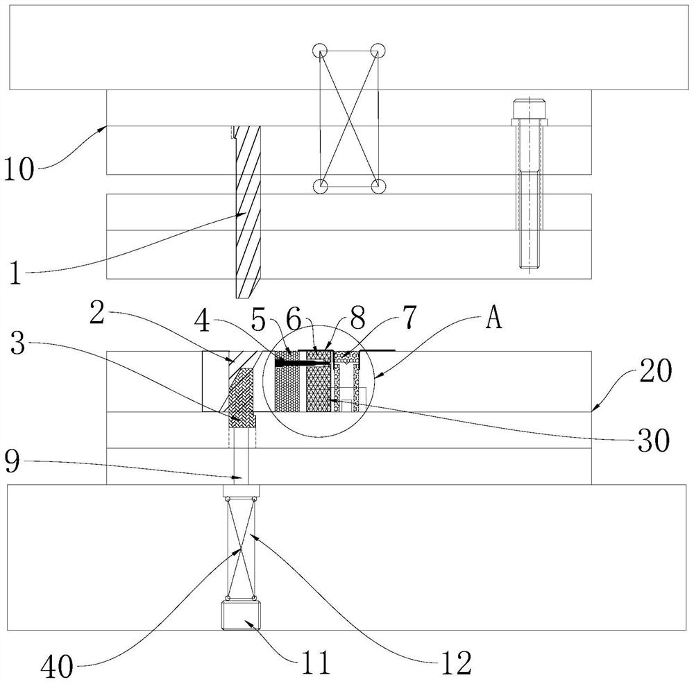
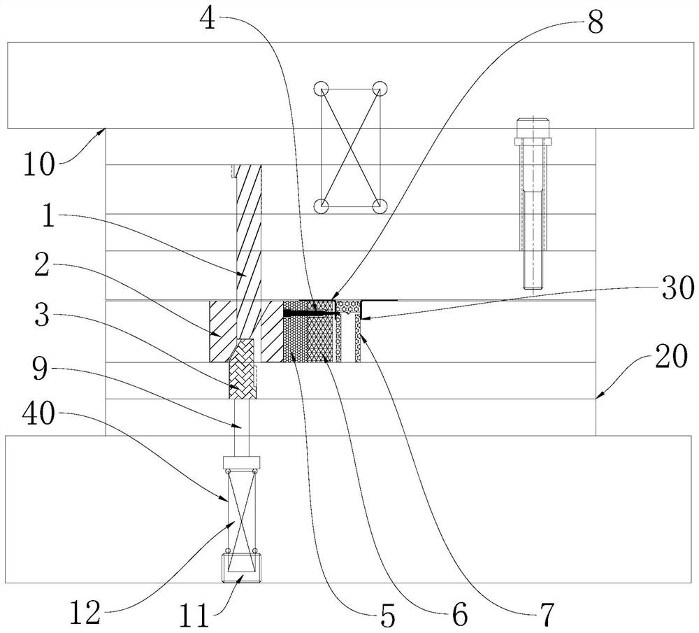
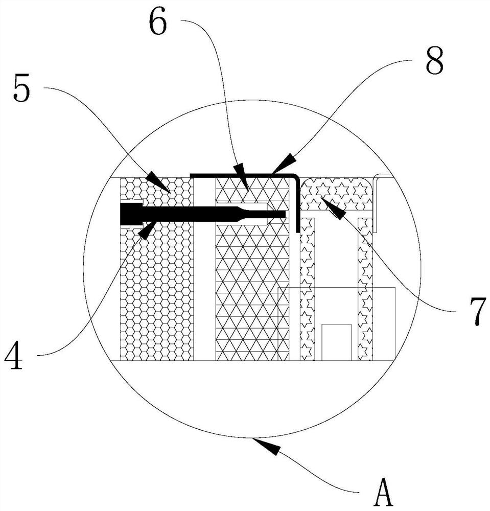
[0019] refer to figure 1 , a lateral punching reset structure, including an upper die assembly 10, a lower die assembly 20, a lateral punching assembly 30 and a reset assembly 40, and the upper die assembly 10 includes an upper die base, an upper backing plate, and an upper splint , stopper plate and stripper plate, and the upper mold base, upper backing plate, upper splint, stopper plate and stripper plate are sequentially connected and fixed from top to bott...


PUM


Abstract

The invention discloses a lateral punching reset structure which comprises an upper die assembly, a lower die assembly, a lateral punching assembly and a reset assembly, the upper die assembly comprises an upper die base, an upper padding plate, an upper clamping plate, a stop plate and a stripper plate, and the upper die base, the upper padding plate, the upper clamping plate, the stop plate and the stripper plate are sequentially connected and fixed from top to bottom; the lower die assembly comprises a lower die plate, a lower clamping plate, a lower cushion plate and a lower die base which are sequentially connected and fixed from top to bottom, the lateral punching assembly comprises an upper die slotting tool, a driving base and a lower die slotting tool, and the upper die slotting tool is vertically and fixedly arranged on the upper die assembly. Lateral punching is conducted on a product, after punching is finished and the upper die is reset, the reset assembly elastically pushes the lower die slotting tool to move upwards, the driving base is driven to move leftwards, the punch is driven to move leftwards, automatic reset is achieved, the reset of the punch is stable and rapid, and the working efficiency is improved.

Description

technical field [0001] The invention relates to the technical field of punching dies, in particular to a lateral punching reset structure. Background technique [0002] At present, the known lateral punching reset method is to install the spring between the punch holder and the punch guide plate. Due to the narrow space, the diameter of the spring is too small and the length is too short, so that the force of the reset spring is not enough and the punching Head reset is unstable and work efficiency is low. Therefore, a stable and efficient lateral punching reset structure is needed. Contents of the invention [0003] The purpose of the present invention is to provide a lateral punching reset structure to solve the problems raised in the above-mentioned background technology. [0004] In order to achieve the above object, the present invention provides the following technical solutions: a lateral punching reset structure, including an upper die assembly, a lower die assem...

Claims


Application Information

Patent Timeline
Patent Type & Authority Applications(China)
IPC IPC(8): B21D28/34
CPCB21D28/34
Inventor 钱晓晨杨勇王玉佳
Owner SUZHOU UIGREEN MICRO & NANO TECH CO LTD
Learn More