
Adjustable center tool apron for numerical control turning machining and using method thereof

A technology for adjusting the center and the tool holder, applied in the field of adjustable center tool holder, it can solve the problems of many styles, affecting the production efficiency of the product, long correction time, etc., and achieve the effect of correcting the coincidence of the rotation center

Pending Publication Date: 2022-02-08
富曜半导体(昆山)有限公司 +1
View PDF0 Cites 0 Cited by
  • Summary
  • Abstract
  • Description
  • Claims
  • Application Information

AI Technical Summary

Problems solved by technology

[0002] The various semiconductor valve body parts undertaken by the factory have the characteristics of many styles and large batches. In the center of the valve body parts, a ball head hole with a surface roughness of Ra0.125μm needs to be processed on a CNC lathe. Due to the limitation of surface roughness, this hole can only be processed by non-standard custom-made ball cutters by means of sockets;
[0003] This kind of operation method often needs a long time for calibration, and there are many uncertain factors. Only the equipment with small center error can be selected for adjustment, and there are also great limitations in equipment selection, which seriously affects the production of products. efficiency, for this reason, an adjustable center tool holder for CNC turning and its application method are proposed

Method used


Image

  • Adjustable center tool apron for numerical control turning machining and using method thereof
  • Adjustable center tool apron for numerical control turning machining and using method thereof
  • Adjustable center tool apron for numerical control turning machining and using method thereof

Examples


Embodiment

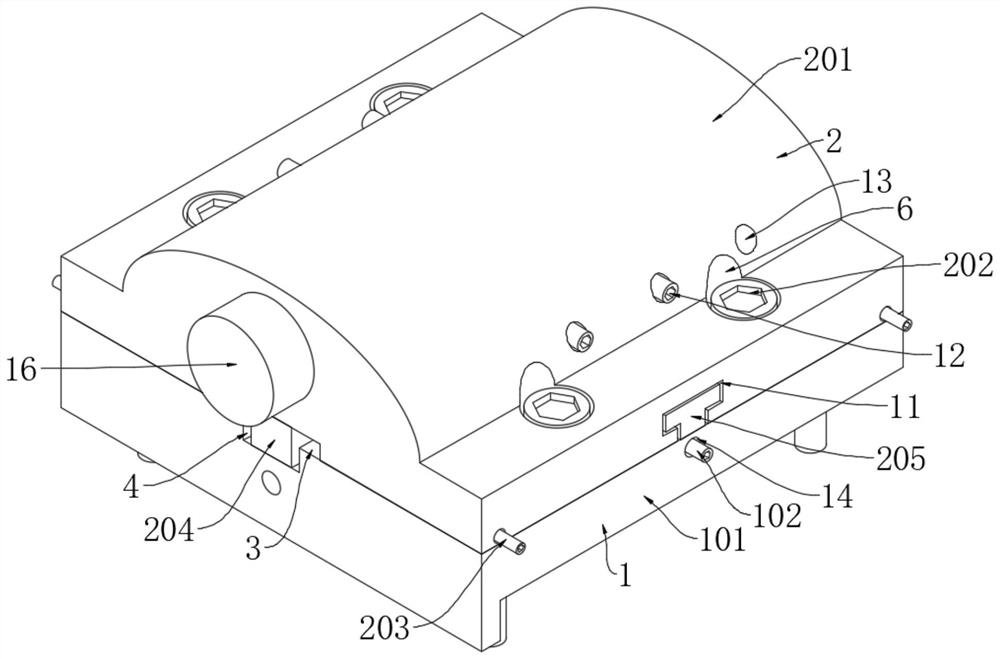
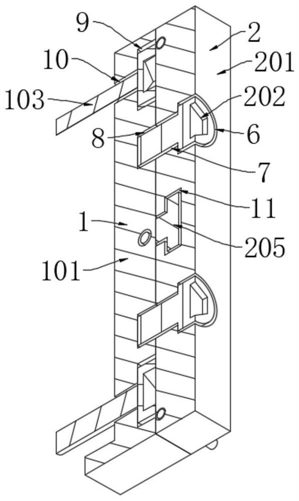
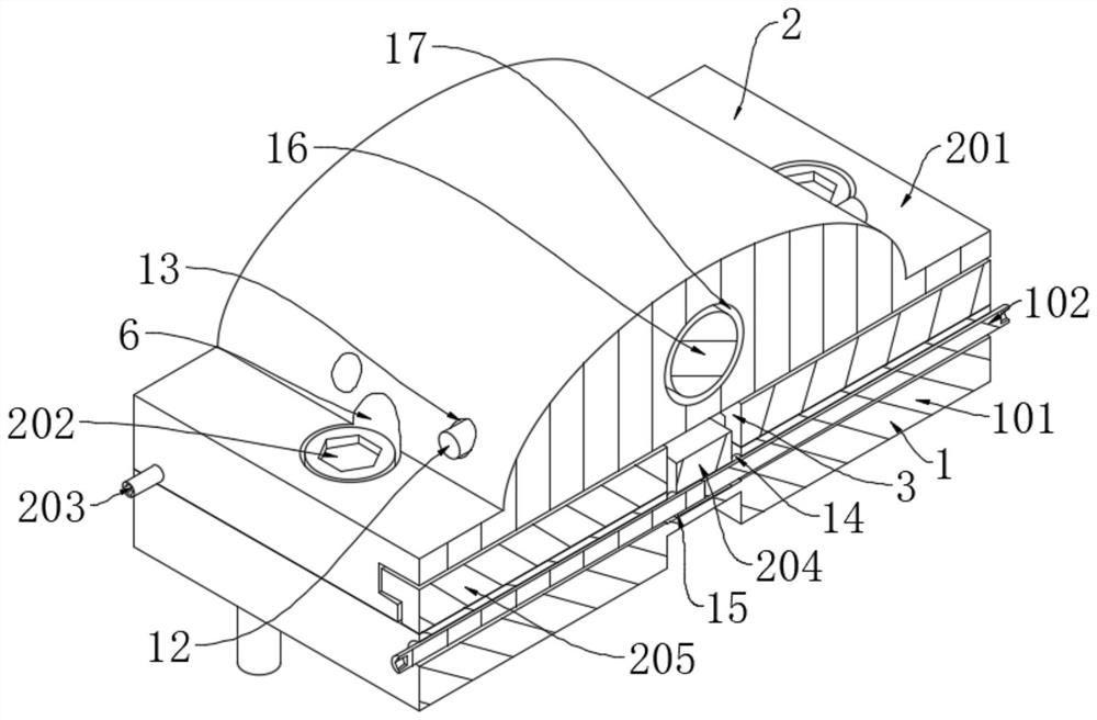
[0030] see Figure 1-5 , the present invention provides a technical solution: an adjustable center tool holder for CNC turning, including a main body assembly 1 and an adjustment and fixing assembly 2, the main body assembly 1 includes a tool holder main body 101, a limit block fixing screw 102 and a tool holder Fixing screw 103;

[0031] An adjustment and fixing assembly 2 is installed on the upper surface of the main body assembly 1;

[0032] The adjustment and fixing assembly 2 includes a floating knife seat body 201, a floating knife seat fixing screw 202, a floating knife seat adjusting screw 203, a limit block body 204 and a T-shaped slider 205;

[0033] The upper surface of the tool seat main body 101 is provided with a second groove 4, the lower surface of the second groove 4 is attached to the outer side wall of the stopper body 204, and one side of the tool seat main body 101 is provided with a fifth threaded through hole 14 The outer wall of the limiting block bod...


PUM


Abstract

The invention discloses an adjustable center tool apron for numerical control turning. The tool apron comprises a main body assembly and an adjusting fixing assembly, and the main body assembly comprises a tool apron main body, a limiting block fixing screw and a tool apron fixing screw; and an adjusting and fixing assembly is mounted on the upper surface of the main body assembly. A floating tool apron body is placed on the tool apron main body, then a limiting block body is moved into a first groove in the tool apron main body and a second groove in the floating tool apron body, and the limiting block fixing screw is rotationally connected into a sixth threaded through hole through a fifth threaded through hole; at the moment, a floating tool apron adjusting screw is rotated in a first threaded through hole to adjust the central position of the floating tool apron body in the tool apron main body; and then the floating tool apron fixing screw is rotated in a second threaded through hole to the threaded groove so as to fasten the positions of the tool apron main body and the floating tool apron body, and the purpose of correcting coincidence of the cutter center and the spindle rotation center is achieved.

Description

technical field [0001] The invention relates to the technical field of precision machining of numerical control lathes, in particular to an adjustable center tool holder for numerical control turning and a method for using the same. Background technique [0002] The various semiconductor valve body parts undertaken by the factory have the characteristics of many styles and large batches. In the center of the valve body parts, a ball head hole with a surface roughness of Ra0.125μm needs to be processed on a CNC lathe. Due to the limitation of surface roughness, this hole can only be processed by non-standard custom-made ball cutters by means of sockets; [0003] This kind of operation method often needs a long time for calibration, and there are many uncertain factors. Only the equipment with small center error can be selected for adjustment, and there are also great limitations in equipment selection, which seriously affects the production of products. Efficiency, for this ...

Claims


Application Information

Patent Timeline
IPC IPC(8): B23B29/04
CPCB23B29/04
Inventor 张海锋张辉李紫栋
Owner 富曜半导体(昆山)有限公司
Learn More