
Portable energy storage device

An energy storage device, portable technology, applied in circuit devices, battery circuit devices, transportation and packaging, etc., can solve the problems of difficult to meet high battery life, heavy product weight, heavy overall weight, etc., to achieve a beautiful and neat appearance and avoid carrying difficulties. , the effect of small footprint

Pending Publication Date: 2022-02-08
CONTEMPORARY NEBULA TECH ENERGY CO LTD
View PDF0 Cites 0 Cited by
  • Summary
  • Abstract
  • Description
  • Claims
  • Application Information

AI Technical Summary

Problems solved by technology

[0003] 1. The weight of the overall product is heavy, it is very bulky when used outdoors, and it is inconvenient to carry;
[0004] 2. The battery storage energy is usually 1KWh, which is difficult to meet the high battery life required by the current market;
[0005] That is to say, the overall weight of mobile energy storage devices currently on the market is too heavy to meet the requirements of high battery life, portability, and weight reduction at the same time. Therefore, a new portable energy storage device is urgently needed to meet the new market demand.

Method used


Image

  • Portable energy storage device
  • Portable energy storage device
  • Portable energy storage device

Examples


Embodiment 1

[0062] Please refer to Figure 1 to Figure 12 , Embodiment 1 of the present invention is:

[0063] A portable energy storage device, including a plurality of energy storage components 1 arranged separately, at least one of the energy storage components 1 is a battery component 1a and at least one is a control component 1b, and the battery component 1a and the control component 1b are electrically connected through wires. connect.

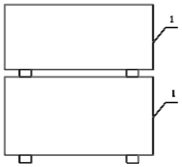
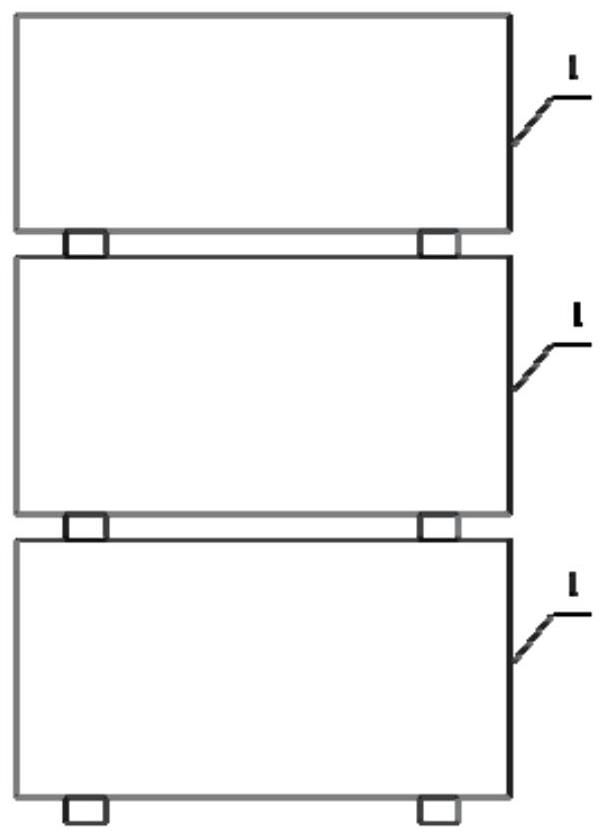
[0064] Wherein, any two energy storage assemblies 1 can be stacked with each other, and the four sides of any two energy storage assemblies 1 are flush with each other after being stacked.

[0065] Such as Figure 4 and Figure 5 As shown, there are two energy storage assemblies 1 in total, including a control assembly 1b and a battery assembly 1a. Wherein, any two energy storage assemblies 1 mentioned above can be stacked with each other, including the mutual stacking of the control assembly 1b and the battery assembly 1a, the mutual stacking o...

Embodiment 2

[0073] Please refer to Figure 1 to Figure 12 , the second embodiment of the present invention is:

[0074] A portable energy storage device. On the basis of the first embodiment above, this embodiment further defines the stacking of two energy storage components 1:

[0075] Such as Figure 6 As shown, the energy storage assembly 1 includes a rotating shaft 111 arranged on the central axis of the upper panel 11, a U-shaped rotating handle 112, an annular boss 114 arranged between the rotating shaft 111 and the rotating handle 112, and an annular boss 114 arranged on the rotating shaft. 111 away from the decorative boss 115 on the side of the rotary handle 112 .

[0076] Wherein, the U-shaped profile of the rotary handle 112 is adapted to the side edge of the upper panel 11 where it is located, and the U-shaped two ends of the rotary handle 112 are rotatably connected with the two ends of the rotary shaft 111 respectively, and the annular boss 114 and the decorative boss 115 ...


PUM


Abstract

The invention discloses a portable energy storage device, which comprises a plurality of energy storage assemblies arranged in a split mode, at least one of the energy storage assemblies is a battery assembly, at least one of the energy storage assemblies is a control assembly, and the battery assembly and the control assembly are electrically connected through an electric wire. Any two energy storage assemblies can be stacked with each other. According to the portable energy storage device, the control assembly and the battery assembly are arranged in a split mode, so that the weight of the whole energy storage device is divided into at least two parts, the portable energy storage device can be distributed to a plurality of persons to be carried during outdoor actual use, the problem that a high-endurance mobile power supply in the current market is too heavy and is difficult to carry is solved, and the outdoor carrying is convenient; and meanwhile, the plurality of battery assemblies can be stacked, so that the plurality of battery assemblies can be carried, the battery assemblies can be rapidly replaced through a battery replacement scheme, the endurance of the energy storage device is improved, the high-power electric appliance requirement of a user is met, and the energy storage device can meet the requirements of portability, weight reduction and endurance improvement at the same time.

Description

technical field [0001] The invention relates to the technical field of outdoor power supplies, in particular to a portable energy storage device. Background technique [0002] In recent years, with the popularity of outdoor sports, outdoor camping projects have become more and more popular among the general public. With the development of the economy, the masses no longer stop at setting up a tent and lighting a bonfire for outdoor camping, but expect to be able to use various household appliances outdoors normally. Therefore, some mobile energy storage devices have appeared on the market. Although the device can solve the needs of the masses for using household appliances outdoors, the mobile energy storage devices currently on the market have the following disadvantages: [0003] 1. The weight of the overall product is heavy, it is very bulky when used outdoors, and it is inconvenient to carry; [0004] 2. The battery storage energy is usually 1KWh, which is difficult to...

Claims


Application Information

Patent Timeline
Patent Type & Authority Applications(China)
IPC IPC(8): H01M50/204H01M50/244H01M50/247H01M50/256H01M50/258H02J7/00
CPCH01M50/204H01M50/244H01M50/247H01M50/256H01M50/258H02J7/0045Y02E60/10
Inventor 石正平叶宝儿陈英李国栋张清芳
Owner CONTEMPORARY NEBULA TECH ENERGY CO LTD
Learn More