Battery holder for tiered battery packs

A technology for battery brackets and battery packs, applied in the direction of battery/battery traction, battery pack components, batteries, etc., which can solve the problems of laborious battery pack costs and unsuitable battery layered installation

Pending Publication Date: 2022-02-15
MICHELIN & CO CIE GEN DES ESTAB MICHELIN
View PDF6 Cites 0 Cited by
  • Summary
  • Abstract
  • Description
  • Claims
  • Application Information

AI Technical Summary

Problems solved by technology

This solution requires the operation of fastening each connector that connects the two batteries to each other using screws and nuts

Method used


Image

  • Battery holder for tiered battery packs
  • Battery holder for tiered battery packs
  • Battery holder for tiered battery packs

Examples


Embodiment Construction

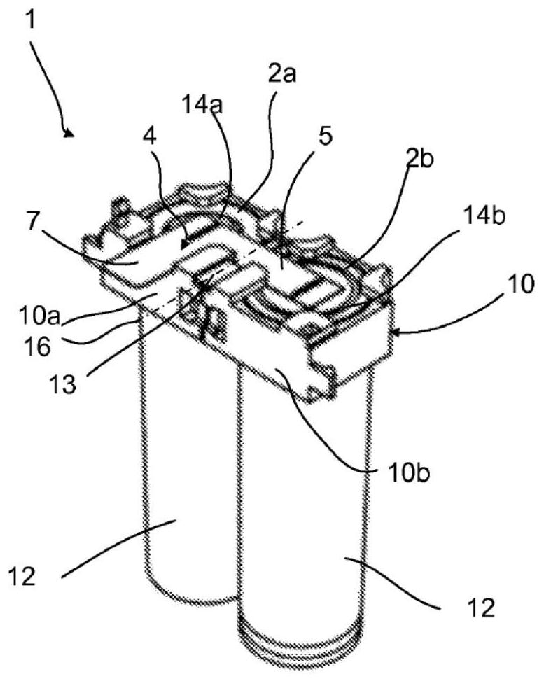
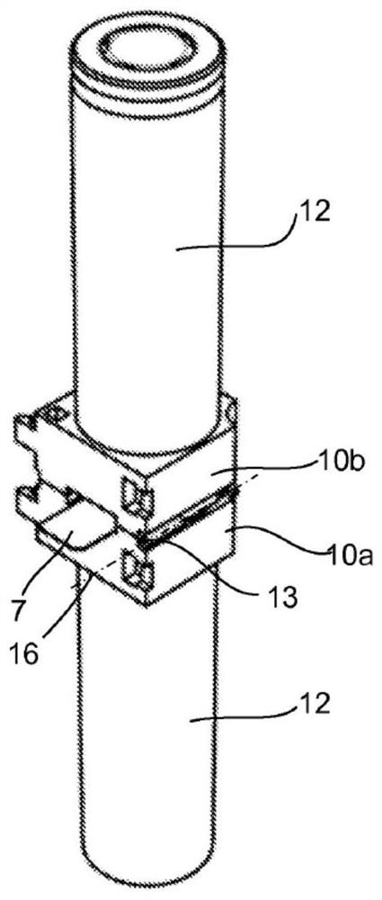
[0048] Figure 1a Shown is a battery holder 10 made in the form of a plate with two adjacent through-holes 2a, 2b made in the thickness of the plate. The plate is produced, for example, by molding or injecting a plastic material of the styrene polymer type, such as ABS (acrylonitrile butadiene styrene), which is an electrically insulating, flame-retardant material. Figure 1a Also shown are two cylindrical batteries 12 held vertically in place by the bracket 10, each battery 12 inserted through one of its ends into a respective hole 2a, 2b of the bracket 10, the longitudinal axis of each battery 12 perpendicular to the plane P of the plate ( figure 2 ). Bracket 10 also comprises connecting elements 4, which are metal sheets, such as nickel or copper, that come into contact with the electrical terminals of battery 12, preferably by welding the metal sheets to the battery's terminals. exist Figure 1a In the embodiment shown, one battery is mounted in hole 2a with its positive...


PUM


Abstract

Disclosed is a battery holder (10) comprising a support plate in the thickness of which at least two adjacent through holes (2a, 2b; 4a, 4b; 6a, 6b; 8a, 8b) are formed, each hole being suitable for receiving, in one hole, the end comprising the terminal (14a) of a first battery (12), and, in the other hole, the end comprising the terminal (14b) of a second battery (12); and a connection element (4, 40) coming into contact with the terminals of the batteries that it connects electrically. According to the invention, the plate comprises two portions (10a, 10b) forming a movable assembly so as to switch from a deployed position in which the two portions (10a, 10b) are arranged side by side in the same plane to a folded position in which the two portions are positioned one on top of the other, the connection element (4, 40) connecting the terminals (14a, 14b) of the batteries (12) in the deployed position and in the folded position.

Description

technical field [0001] The invention relates to the field of battery systems for mobile systems, such as vehicles, or for stationary storage, in particular of the type comprising an arrangement of a plurality of cells forming a layered battery pack. Background technique [0002] The battery pack itself usually consists of multiple individual cells connected to each other. These cells can have various geometries such as prismatic, pouch or cylindrical. They are electrically connected according to the requirements of the application to form series and parallel battery combinations. To this end, it must be possible to connect their electrodes via conductive elements, which can be screwed or welded to their terminals, for example. For some applications where the current through the batteries is low, there may be stacks of batteries where the batteries are not firmly connected to each other but simply in contact (eg in portable radios). However, for most applications, when hig...

Claims


Application Information

Patent Timeline
IPC IPC(8): H01M50/213H01M50/244H01M50/249H01M50/251H01M50/503H01M50/502
CPCH01M50/213H01M50/244H01M50/249H01M50/251H01M50/503H01M50/502H01M2220/20H01M10/613H01M10/6557H01M10/643B60L50/64H01M50/256H01M50/20Y02T10/70Y02E60/10Y02P70/50H01M50/516H01M50/262
Inventor B·弗拉尼耶D·瓦尔泽
Owner MICHELIN & CO CIE GEN DES ESTAB MICHELIN
Why Eureka
Try Eureka