Fluid heat exchange test device

A heat test and fluid technology, which is applied in the field of fluid heat exchange test equipment, can solve the problem of difficult dirt inside the narrow slit channel

Pending Publication Date: 2022-02-18
SHANGHAI JIAO TONG UNIV
View PDF0 Cites 0 Cited by
  • Summary
  • Abstract
  • Description
  • Claims
  • Application Information

AI Technical Summary

Problems solved by technology

[0005] The purpose of the present invention is to provide a fluid heat exchange test device to solve the current technical problem that it is difficult to sample the dirt inside the narrow slit channel

Method used


Image

  • Fluid heat exchange test device
  • Fluid heat exchange test device
  • Fluid heat exchange test device

Examples


Embodiment Construction

[0035] In order to make the above objects, features, and advantages of the present invention, the specific embodiments of the present invention will be described in detail below with reference to the accompanying drawings. It is to be understood that the specific embodiments described herein are intended to explain the present invention and is not intended to limit the invention.

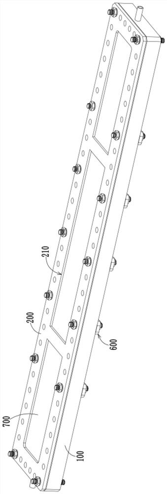
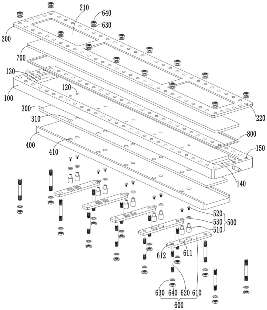
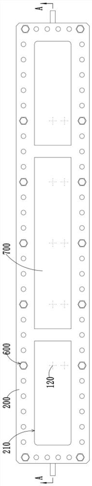
[0036] figure 1 Structure of the fluid heat exchange test device provided in this example, figure 2 The structural exploded view of the fluid heat exchange test device provided in this embodiment, image 3 A structural top view of the fluid heat exchange test device provided in this example, Figure 4 for image 3 A cross-sectional view of the A-A, Figure 5 for Figure 4 The local structure enlarged in Central B. Such as Figure 1 to 5 As shown, the present embodiment provides a fluid heat transfer test device, including the experimental plate 100, the bond plate 200, and the heating member 300, wherein the...


PUM


Abstract

The invention provides a fluid heat exchange test device, and relates to the technical field of fluid test equipment. The device is designed for solving the problem of high difficulty in sampling dirt in a narrow slit channel at present. The fluid heat exchange test device comprises an experiment plate, a clamping plate, a heating part and a sampling assembly. The clamping plate and the experiment plate are arranged in a stacked mode and form a narrow-slit channel used for fluid flowing, the heating part is configured to provide heat for the narrow-slit channel, the experiment plate is provided with at least one set of sampling holes, and the sampling holes communicate with the narrow-slit channel. The sampling assembly is detachably installed in the sampling hole, and the sampling part of the sampling assembly is flush with the channel surface of the narrow channel. The fluid heat exchange test device provided by the invention can conveniently realize sampling operation of dirt in the narrow slit channel.

Description

Technical field [0001] The present invention relates to the technical findings of fluid test equipment, and in particular, therefore involve a fluid heat exchange test device. Background technique [0002] In industrial production, the heat exchange and cooling conditions of the narrow space are often encountered, such as the process of heat exchange, or the microelectronic heat exchange sheet for heat transfer process, which is through fluid in a narrow slit. The flow in the channel is incorporated or transmitted, thereby completing heat exchange. The prior art narrow slit channel is typically formed by a gap between 1-3 mm between the two coupling plates, and the plate-shaped heat exchanger formed by the narrow seam passage is more structured. Compact, smaller volume, and higher heat transfer efficiency. [0003] In the process of fluid heat transfer studies using a narrow slit passage, when the fluid is changed to a quantity of negative soluble salts, a layer of soil is easily...

Claims


Application Information

Patent Timeline
Patent Type & Authority Applications(China)
IPC IPC(8): G01N25/20
CPCG01N25/20
Inventor 刘晓晶许巍段钟弟程成丁书华吴丹
Owner SHANGHAI JIAO TONG UNIV
Why Eureka
Try Eureka