
Valve position calibration method, device and system and storage medium

A technology of calibration system and calibration method, which is applied in general control system, control/regulation system, program control, etc., can solve problems such as correction errors, and achieve the effects of simplifying installation requirements, reducing control errors, and controlling accurately

Pending Publication Date: 2022-02-18
ZHEJIANG SUPCON TECH +1
View PDF0 Cites 1 Cited by
  • Summary
  • Abstract
  • Description
  • Claims
  • Application Information

AI Technical Summary

Problems solved by technology

[0004] If the conditions of on-site installation do not meet the requirements, or the user makes a mistake in his own judgment, there will be a large error in the correction, and there are certain limitations.

Method used


Image

  • Valve position calibration method, device and system and storage medium
  • Valve position calibration method, device and system and storage medium
  • Valve position calibration method, device and system and storage medium

Examples


Embodiment Construction

[0056] In order to make the purpose, technical solutions and advantages of the embodiments of the present invention clearer, the technical solutions in the embodiments of the present invention will be clearly and completely described below in conjunction with the drawings in the embodiments of the present invention. Obviously, the described embodiments It is a part of embodiments of the present invention, but not all embodiments. The components of the embodiments of the invention generally described and illustrated in the figures herein may be arranged and designed in a variety of different configurations.

[0057] Accordingly, the following detailed description of the embodiments of the invention provided in the accompanying drawings is not intended to limit the scope of the claimed invention, but merely represents selected embodiments of the invention. Based on the embodiments of the present invention, all other embodiments obtained by persons of ordinary skill in the art wi...


PUM


Abstract

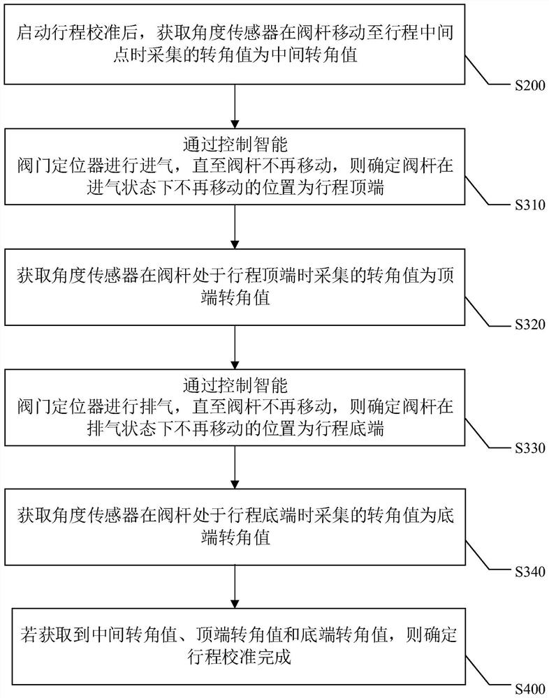
The embodiment of the invention provides a valve position calibration method, device and system and a storage medium, which relate to the field of valve positioner control. The method comprises the steps that after stroke calibration is started, a corner value collected by an angle sensor when a valve rod moves to a stroke middle point is obtained and serves as a middle corner value; the intelligent valve positioner is controlled to carry out air intake until the valve rod does not move any more, and the position where the valve rod does not move any more in the air intake state is determined as the stroke top end; a corner value acquired by the angle sensor when the valve rod is located at the top end of the stroke is obtained as a top corner value; the intelligent valve positioner is controlled to exhaust until the valve rod does not move any more, and the position where the valve rod does not move any more in the exhaust state is determined as the stroke bottom end; a corner value collected by the angle sensor when the valve rod is located at the stroke bottom end is obtained as a bottom end corner value; if the corner values of the middle end, the top end and the bottom end are obtained, it is determined that stroke calibration is completed. Thus, the control precision of the valve can be improved.

Description

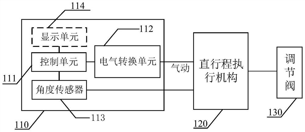
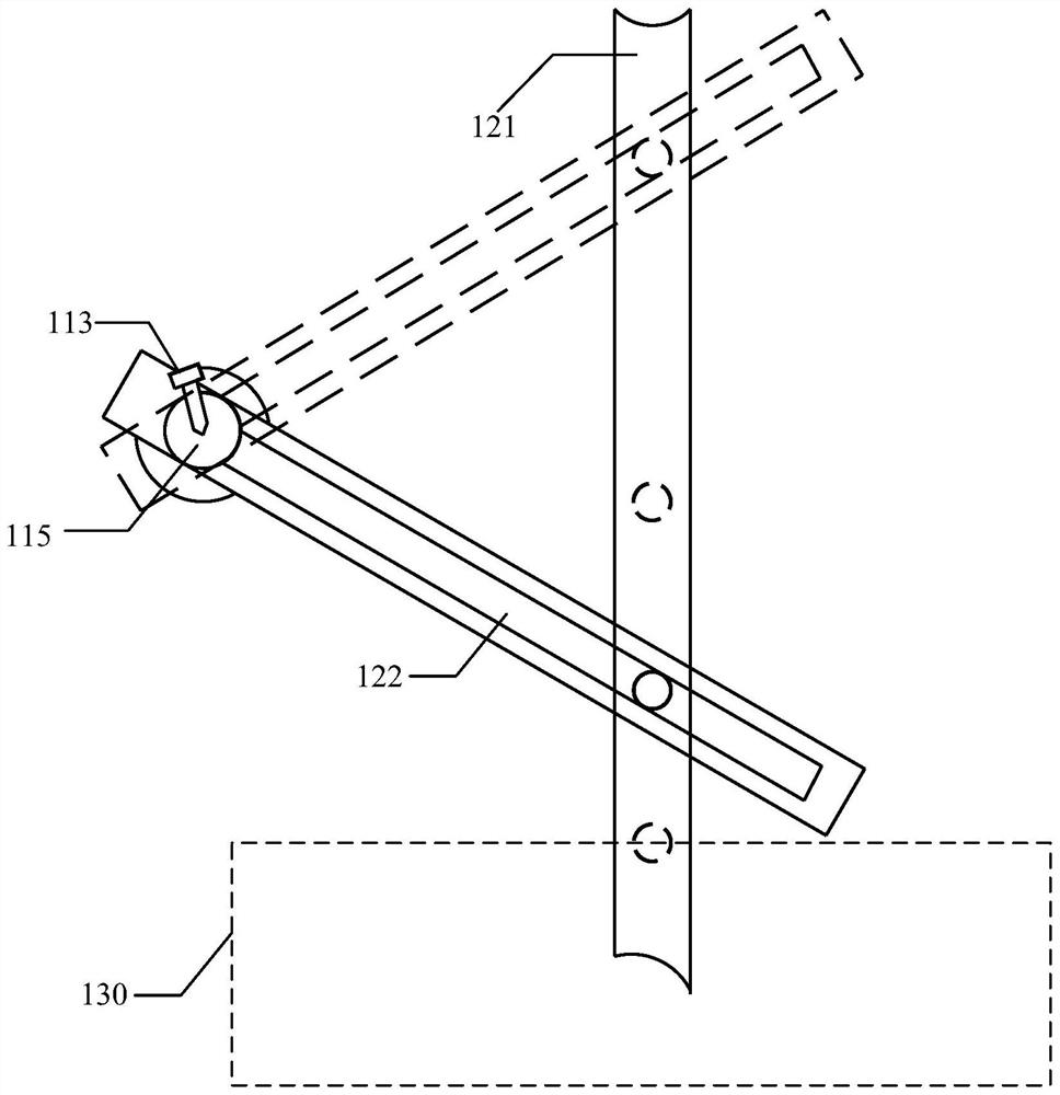
technical field [0001] The invention relates to the field of valve positioner control, in particular to a valve position calibration method, device, system and storage medium. Background technique [0002] In industrial development, valve positioners can assist regulating valves to achieve flow control and play an important role. When the valve positioner controls the linear actuator, due to the non-linear relationship between the stroke of the valve stem and the rotation angle of the connecting rod, the regulating valve often cannot be adjusted to the preset position according to the demand. [0003] The existing method of calibrating the valve position greatly depends on the user's own experience, and there are certain on-site installation requirements, such as requiring the valve stem to be perpendicular to the connecting rod when the valve stem is in the middle position. [0004] If the conditions of on-site installation do not meet the requirements, or the user makes a...

Claims


Application Information

Patent Timeline
Patent Type & Authority Applications(China)
IPC IPC(8): G05B19/042G06V40/16
CPCG05B19/0423G05B2219/24215
Inventor 胡孟杰薛斌赵克安
Owner ZHEJIANG SUPCON TECH
Learn More