Variable optical attenuator-based bus current detection method and current transformer equipment

A technology of dimming attenuation and bus current, applied in the direction of measuring current/voltage, voltage/current isolation, instruments, etc., can solve the problems of high power consumption, unstable measurement, etc., reduce power supply demand, eliminate optical attenuation constant drift, Effects on Solving Nonlinear Problems

Active Publication Date: 2013-11-20
SOUTHEAST UNIV
View PDF11 Cites 16 Cited by
  • Summary
  • Abstract
  • Description
  • Claims
  • Application Information

AI Technical Summary

Problems solved by technology

[0007] Aiming at the problems of high power consumption and unstable measurement existing in existing electronic transformers, the present invention proposes a bus current detection method based on an adjustable optical attenuator and current transformer equipment that can reduce power consumption and improve measurement accuracy

Method used


Image

  • Variable optical attenuator-based bus current detection method and current transformer equipment
  • Variable optical attenuator-based bus current detection method and current transformer equipment
  • Variable optical attenuator-based bus current detection method and current transformer equipment

Examples


Embodiment 1

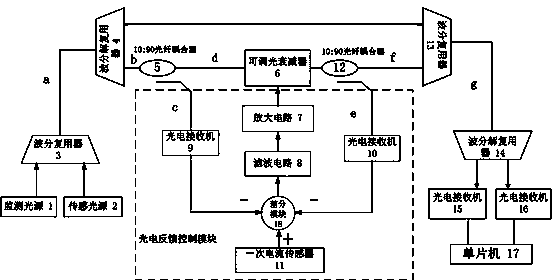
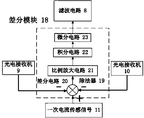
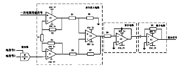
[0019] refer to figure 1, a bus current detection method based on an adjustable optical attenuator. The monitoring light and the sensing light are respectively generated by the monitoring light source 1 and the sensing light source 2. The sensing light is photoelectrically converted after passing through the adjustable optical attenuator 6. At the same time, Use the first optical fiber coupler 5 and the second optical fiber coupler 12 to respectively collect the input optical signal and output optical signal of the adjustable optical attenuator 6 and perform photoelectric conversion on the input optical signal and output optical signal, and use the primary current sensor 11 to obtain the high-voltage line The current signal of the bus on the bus and generate a current sensing signal, and then perform differential calculations on the primary current sensing signal and the input optical signal and output optical signal after photoelectric conversion, refer to figure 2 The obtai...

Embodiment 2

[0021] refer to figure 1 , a current transformer device, comprising: a monitoring light source 1, a sensing light source 2, a first wavelength division multiplexer 3, a first wavelength division multiplexer 4, an adjustable optical attenuator 6, a second wavelength division multiplexer 13, the second wave division multiplexer 14, the third photoelectric receiver 15, the fourth photoelectric receiver 16, the single chip microcomputer 17 and the photoelectric feedback control module, the monitoring light source 1 and the sensing light source 2 are respectively connected with the first wave division The two input terminals of the multiplexer 3 are connected, the output terminal of the first wavelength division multiplexer 3 is connected with the input terminal of the first wavelength division multiplexer 4, and an output terminal of the first wavelength division multiplexer 4 is connected with the second wavelength division multiplexer 4. An input end of the wavelength division m...


PUM


Abstract

The invention discloses a variable optical attenuator-based bus current detection method and current transformer equipment. The method comprises the following steps: generating monitoring light and sensing light by a monitoring light source and a sensing light source respectively, wherein the sensing light passes through a variable optical attenuator to generate an attenuated optical signal, is subjected to photoelectric conversion with the monitoring light respectively and then is input into a single-chip microprocessor for algorithmic processing so as to generate a secondary current signal; meanwhile, acquiring a bus current signal on a high-voltage line by using a primary current sensor, and differentiating, filtering and amplifying with feedback electric signals of an input signal and an output signal of the variable optical attenuator to generate a new driving signal for driving the variable optical attenuator. The equipment comprises the monitoring light source, the sensing light source, the variable optical attenuator, two wavelength division multiplxers, two photoelectric receivers, the single-chip microprocessor and a photoelectric feedback control module, wherein the photoelectric feedback control module comprises two photoelectric receivers, a differential module, a filter circuit and an amplifying circuit.

Description

technical field [0001] The invention belongs to the field of power system monitoring and protection. In particular, it relates to a bus current detection method and current transformer equipment based on an adjustable optical attenuator in a power system. Background technique [0002] Transformer is an important equipment in the power system, its accuracy and reliability are closely related to the safety, reliability and economical operation of the power system. Traditional transformers are mainly electromagnetic transformers. With the continuous development of science and technology, a series of serious errors have been exposed in the operation of electromagnetic transformers, including complex structure, high cost, easy saturation and inaccurate ferromagnetic resonance measurement. With the improvement of the operating voltage level of my country's power grid, the design of the traditional transformer insulation structure has become extremely complicated, and its cost and...

Claims


Application Information

Patent Timeline
Patent Type & Authority Applications(China)
IPC IPC(8): G01R19/00G01R15/18
Inventor 韦朴王雪峰孙小菡单雪康
Owner SOUTHEAST UNIV
Why Eureka
Try Eureka