Rotor levitation centre determination method for permanent magnet motor-driven maglev molecular pump

A permanent magnet motor and magnetic levitation technology, applied in the direction of measuring device, using electric device, using electromagnetic means, etc., to achieve the effect of accurate acquisition and elimination of magnetic bias pulling force

A permanent magnet motor and magnetic levitation technology, applied in the direction of measuring device, using electric device, using electromagnetic means, etc., to achieve the effect of accurate acquisition and elimination of magnetic bias pulling force

CN102435135AActive Publication Date: 2012-05-02KYKY TECH +1

Image

  • Rotor levitation centre determination method for permanent magnet motor-driven maglev molecular pump
  • Rotor levitation centre determination method for permanent magnet motor-driven maglev molecular pump
  • Rotor levitation centre determination method for permanent magnet motor-driven maglev molecular pump

Examples


Embodiment Construction

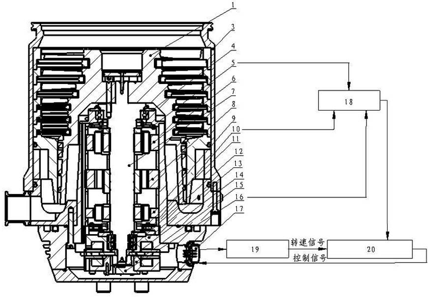
[0031] Such as figure 1 As shown, it is a structural schematic diagram of the magnetic levitation molecular pump involved in the present invention. As an embodiment of the present invention, the method for measuring the rotor levitation center of the magnetic levitation molecular pump driven by the permanent magnet motor includes the following steps:

[0032] Step S01, using the rotor of the magnetic levitation molecular pump without the rotor magnet of the motor as a test rotor, and loading the test rotor into the molecular pump;

[0033] Step S02 obtains the radial suspension center of the test rotor: first, place the magnetic levitation molecular pump vertically, put the test rotor into the magnetic levitation molecular pump, use the magnetic levitation molecular pump controller 20 to control the static levitation of the test rotor, and obtain the first The electric current in each magnetic pole coil of radial magnetic bearing 6; Then, compare whether the current amplitudes...


PUM


Abstract

The invention relates to a rotor levitation centre determination method for a permanent magnet motor-driven maglev molecular pump. A testing rotor for eliminating the magnetic field of permanent magnet motor rotor steel magnets is utilized, and by means of a method which adjusts the levitation centre of the testing rotor to guarantee the current equilibrium of each magnetic pole of magnetic bearings, the levitation centre of a rotor of the maglev molecular pump is obtained. The testing rotor eliminates the affection of the magnetic bias pull of the rotor of a permanent magnet motor, and the levitation centre of the rotor of the maglev molecular pump can be accurately obtained.

Description

technical field [0001] The invention relates to a method for measuring the rotor suspension center of a magnetic suspension molecular pump, in particular to a method for measuring the rotor suspension center of a magnetic suspension molecular pump driven by a permanent magnet motor. Background technique [0002] Molecular pump is a kind of vacuum pump, which uses high-speed rotating rotor impeller to transfer momentum to gas molecules to obtain directional speed, so that the gas is compressed, driven to the exhaust port, and then pumped away by the backing pump. The magnetic levitation molecular pump is a molecular pump that uses magnetic bearings as the rotor support of the molecular pump. It uses magnetic bearings to suspend the rotor stably in the air, so that there is no mechanical contact between the rotor and the stator during high-speed operation, and it has no mechanical wear, With the advantages of low energy consumption, high allowable speed, low noise, long life, ...

Claims


Application Information

Patent Timeline
02 May 2012
Publication
CN102435135A
IPC
G01B7/312
Inventors
张剀; 武涵