Armature assembly

A pipe joint, direct technology, applied in the direction of valve device, pipe/pipe joint/pipe fitting, valve operation/release device, etc., can solve problems such as pressure loss, large resistance coefficient, differential regulation, etc.

Pending Publication Date: 2022-02-18
KSB AG
View PDF7 Cites 0 Cited by
  • Summary
  • Abstract
  • Description
  • Claims
  • Application Information

AI Technical Summary

Problems solved by technology

However, it is problematic here that, despite the large clearances, on the other hand, even in the fully open operating state, a very high drag coefficient is associated with it.
On the other hand, for example, shutters, slides or cocks do not have great power, that is to say they can only be adjusted poorly, but they also cause only a small pressure loss in the fully open state for this purpose.

Method used


Image

  • Armature assembly
  • Armature assembly
  • Armature assembly

Examples


Embodiment Construction

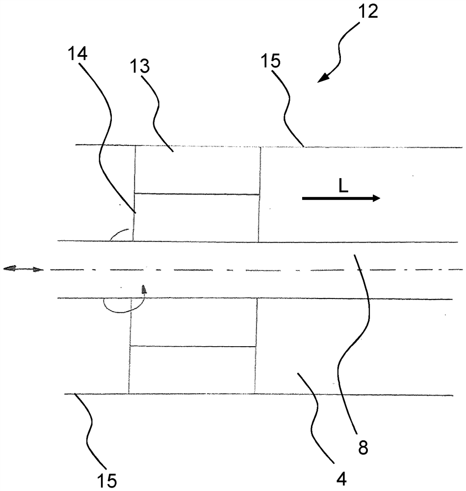
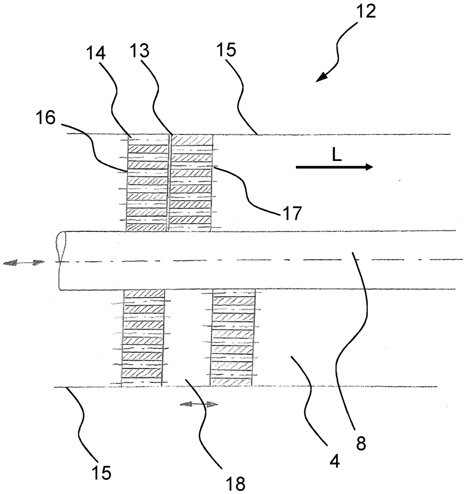
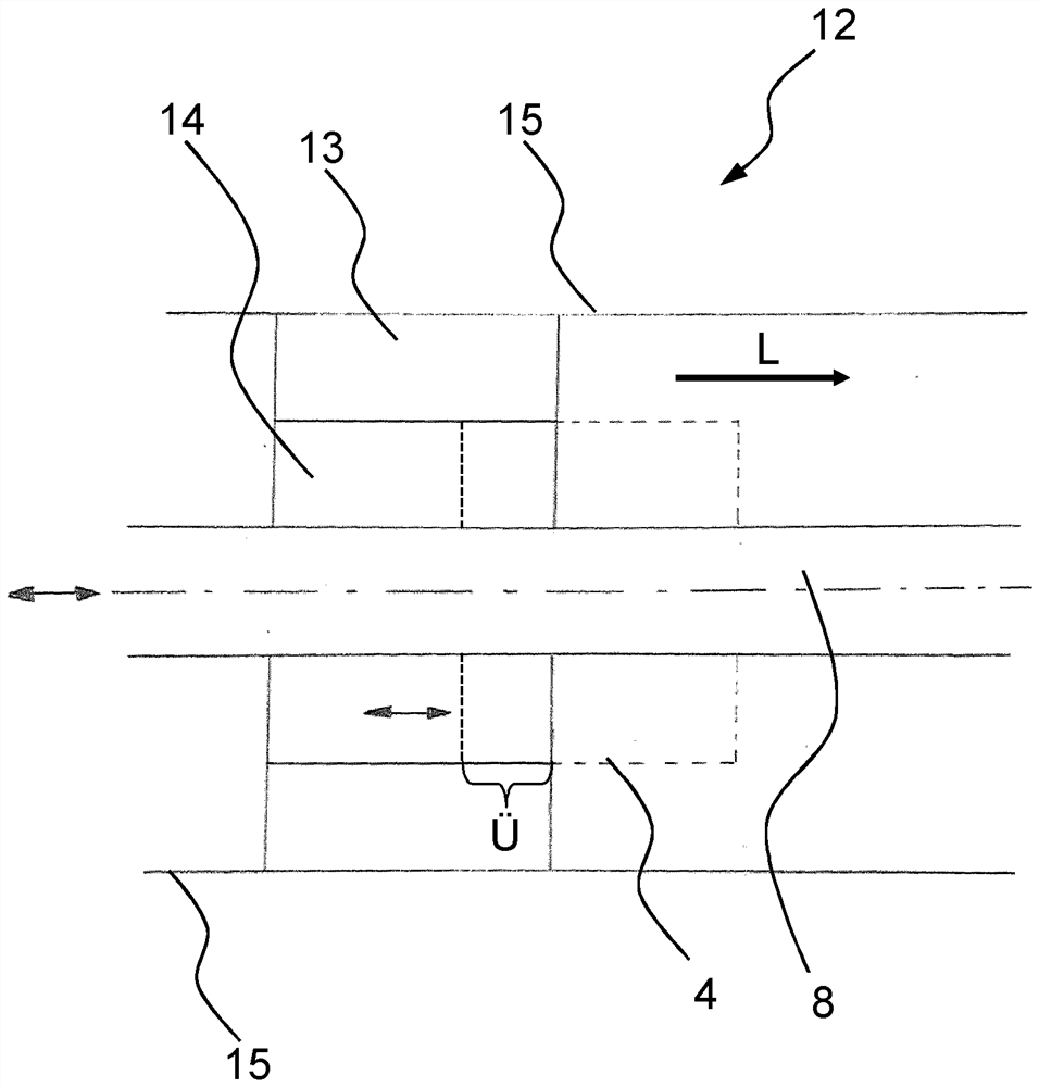
[0033] figure 1 A pipe connection arrangement according to the invention is shown. The pipe connection arrangement has a housing 1 which can be installed at both ends via flanges 9 in each case in a flow-guiding device, for example a pipe. The flange 9 has bores for receiving fastening means. This is preferably a screw connection.

[0034] A channel 4 is provided in the housing 1 , which opens into the first and the second opening 2 , 3 at the end of the housing 1 . In an operating state, the connector arrangement is operated such that the first opening 2 is configured as an inlet opening for a fluid flow and the second opening 3 is configured as an outlet opening for a fluid flow. The working medium thus flows counter to the channel direction L shown.

[0035] The channel 4 has no bends along the channel direction L. This means that the fluid flow is not deflected by the housing or that the center point of the area of ​​the cross section of the channel 4 is arranged at a...


PUM


Abstract

The invention relates to an armature assembly comprising a housing (1), two openings (2, 3), and a channel (4) which extends in the housing (1) between the openings (2, 3). A primary throttle module (6) is movably arranged in a throttle section (5) of the channel (4) such that the throttle module limits the cross-section of the channel (4) in the throttle section (5). According to the invention, the channel (4) is equipped with at least one secondary throttle module (12) consisting of at least a first and a second throttle element (13, 14) upstream or downstream of the primary throttle module (6) in the channel direction (L), wherein the throttle elements (13, 14) of the secondary throttle module (12) can be moved relative to each other such that, in an operational state, the flow resistance of a flowing fluid is changed according to the position of the throttle elements (13, 14).

Description

technical field [0001] The invention relates to a pipe connection device having a housing, at least two openings and a channel extending between the openings in the housing, wherein a primary throttle module is arranged in such a manner that it can move in the In the throttle section of the channel, the primary throttle module limits the cross section of the channel in the throttle section. Background technique [0002] Such connection arrangements are often used in installations for conveying fluids, such as liquids, vapors or gases, in order to be able to regulate or control the conveying situation in a targeted manner. At the same time, it is also possible to completely block the connection device, thereby interrupting the supply of the corresponding fluid. [0003] The design of such a connection arrangement is based on safety-related aspects on the one hand and flow-technical considerations on the other hand. For example, in the fully open operating state, the flow co...

Claims


Application Information

Patent Timeline
Patent Type & Authority Applications(China)
IPC IPC(8): F16L29/00
CPCF16L29/00F16L29/005F16K1/12F16K1/52F16K1/526F16K1/54F16K31/54F16K47/04F16K47/045F16K47/08
Inventor D·哈内瓦尔德G·劳奇
Owner KSB AG
Why Eureka
Try Eureka