Suction cleaning device with sieve element

A technology for cleaning equipment and sieve elements, used in cleaning equipment, suction filters, vacuum cleaners, etc., can solve problems such as reducing the tendency of clogging

Pending Publication Date: 2021-07-27
VORWERK & CO INTERHOLDING GMBH
View PDF0 Cites 0 Cited by
  • Summary
  • Abstract
  • Description
  • Claims
  • Application Information

AI Technical Summary

Problems solved by technology

[0004] Based on the prior art described above, the technical problem to be solved by the present invention is to equip a suction cleaning device with a sieve element which does not have the above-mentioned disadvantages, that is to say in which the tendency to clogging is reduced or even completely eliminated

Method used


Image

  • Suction cleaning device with sieve element
  • Suction cleaning device with sieve element
  • Suction cleaning device with sieve element

Examples


Embodiment Construction

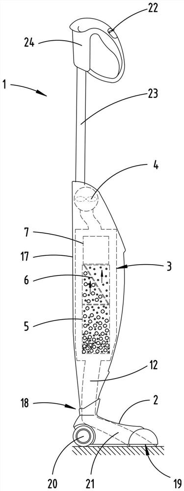
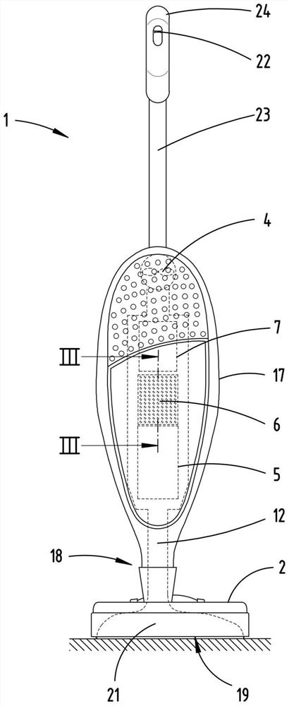
[0044] figure 1 An extraction cleaning device 1 , here a hand-held vacuum cleaner for example, is shown by way of example with a base device 17 and a suction nozzle 2 as a detachable accessory device. The suction nozzle 2 has a suction opening 19 through which suction material can be collected from the surface to be cleaned into the suction cleaning device 1 . To simplify the movement of the suction cleaning device 1 over the surface to be cleaned, the suction nozzle 2 has wheels 20 . The basic device 17 and the suction nozzle 2 are detachably connected to one another via a connecting region 18 so that the suction nozzle 2 can be optionally exchanged for another suction nozzle 2 . On the base device 17 there is a handle 23 with a handle 24 by means of which the user can guide the suction cleaning device 1 over the surface to be cleaned. This usually occurs in a continuous reciprocating movement. The handle 23 is preferably designed to be telescopic so that the user can adju...


PUM


Abstract

The invention relates to a suction cleaning device with a suction nozzle, a suction material separating device and a fan, which are fluidically connected to each other in such a way that suction material can be transported to the suction material separating device by means of the fan via the suction nozzle, wherein the suction material separating device has a first separation device for coarse material, a sieve element having a plurality of through openings, and a second separation device for fine dust in the direction of flow of the suction material. In order to prevent suction material particles from getting stuck inside the sieve element, it is proposed that the sieve element is designed independently of the first separation device and the second separation device in function and is designed independently of the first separation device and the second separation device in structure, wherein the inner wall of the through opening is oriented obliquely with respect to the plane normal of the opening plane of the through opening so as to form an acute angle, and the inner wall of the opening has an angle in particular between 30 degrees and 75 degrees with respect to the plane normal.

Description

technical field [0001] The invention relates to a suction cleaning device with a suction nozzle, a suction separation device and a fan, which are flow-connected to each other so that the suction can be separated by means of the fan. via the suction nozzle to the aspirate separating device, wherein the aspirate separating device has a first separating device for the coarse material, a sieve element with a plurality of through holes and a Secondary separation device for dust. Background technique [0002] Suction cleaning devices are sufficiently known in the prior art. The suction cleaning device can be designed, for example, as a household or industrial vacuum cleaner. In addition, different types of suction cleaning appliances are known, such as bagless vacuum cleaners and vacuum cleaners with filter bags. Bagless vacuum cleaners include, for example, so-called cyclone dust collectors and vacuum cleaners with so-called permanent filters, which can be regenerated as requi...

Claims


Application Information

Patent Timeline
Patent Type & Authority Applications(China)
IPC IPC(8): A47L9/12A47L9/10
CPCA47L9/102A47L9/122A47L5/28A47L9/10
Inventor J.巴豪森I.艾林W.迈耶
Owner VORWERK & CO INTERHOLDING GMBH
Why Eureka
Try Eureka