Supercharge Your Innovation With Domain-Expert AI Agents!

Intelligent instrument protection device

A technology of instrumentation and protection devices, which is applied in the field of intelligent instrumentation protection devices, can solve problems such as cumbersome operations, and achieve the effect of reducing troubles

Active Publication Date: 2022-03-01
JIANGXI HJATIS POWER IND CO LTD
View PDF7 Cites 0 Cited by
  • Summary
  • Abstract
  • Description
  • Claims
  • Application Information

AI Technical Summary

Problems solved by technology

[0005] In order to overcome the disadvantages of the prior art that each time an instrument is placed, it is necessary to plug in a barrier plate and limit the position of the instrument, which is a cumbersome operation. The purpose of the present invention is to provide an intelligent instrument protection device that is easy to operate.

Method used


Image

  • Intelligent instrument protection device
  • Intelligent instrument protection device
  • Intelligent instrument protection device

Examples


Embodiment 1

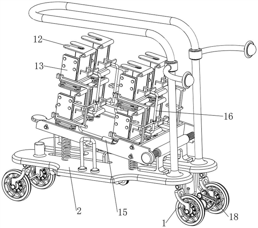
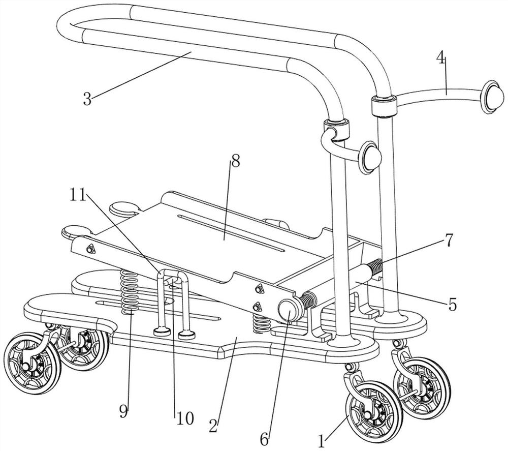
[0040] An intelligent instrument and meter protection device, referring to Figure 1-6 , including a wheel 1, a bottom plate 2, a first pull rod 3, a second pull rod 4, a first fixed column 5, a rotating shaft 6, a torsion spring 7, a first supporting plate 8, a first linear spring 9, a limit rod 10, Limiting frame 11, placing mechanism 12 and anti-collision mechanism 13, the left and right sides of base plate 2 lower sides are all rotatably provided with wheel 1, and wheel 1 is used for moving this intelligent instrument protection device, and wheel 1 top right side is provided with the first A pull rod 3, the first pull rod 3 is used for people to manually pull the intelligent instrument protection device, the front and rear sides of the upper right side of the first pull rod 3 are provided with a second pull rod 4, and the second pull rod 4 is used for people to manually push the smart instrument. Instrument protection device, the top right side of the bottom plate 2 is pro...

Embodiment 2

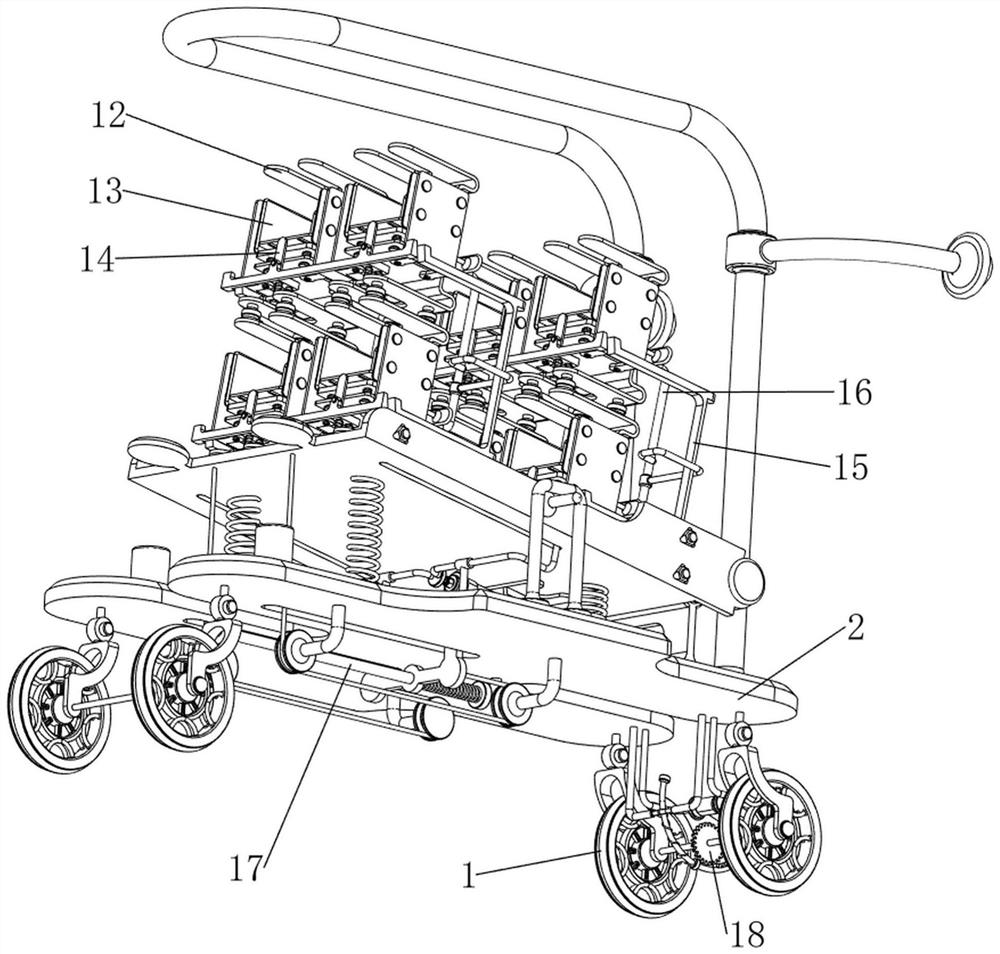
[0045] On the basis of embodiment 1, refer to figure 2 and Figure 7 , also includes a limit mechanism 14 for limiting the left side of the smart instrument, the limit mechanism 14 includes a fourth fixed plate 141, a third slide bar 142, a limit plate 143 and a fourth linear spring 144, four The upper and lower sides of the first fixed plate 121 are fixedly connected with a fourth fixed plate 141 by bolts, and the fourth fixed plate 141 is slidably provided with two third slide bars 142, between the tops of the two third slide bars 142. Limiting plates 143 are arranged between them, and the limiting plates 143 block the left side of the intelligent instrument. Two fourth linear springs 144 are connected between the limiting plates 143 and the fourth fixed plate 141 on the same side. The fourth linear springs 144 Both are sleeved on the third slide bar 142 on the same side.

[0046] Manually move down the limit plate 143 to put it away, the fourth linear spring 144 is compr...


PUM


Abstract

The invention relates to a protection device, in particular to an intelligent instrument and meter protection device. The invention provides an intelligent instrument and meter protection device which is simple to operate. An intelligent instrument and meter protection device comprises wheels, a bottom plate, a first pull rod, second pull rods, a first fixing column, a rotating shaft and the like, the wheels are rotationally arranged on the left side and the right side of the lower side of the bottom plate, the first pull rod is arranged on the right side of the top of each wheel, and the second pull rods are arranged on the front side and the rear side of the right side of the upper portion of each first pull rod; the first fixing column is located on the left side of the first pull rod. The intelligent instruments and meters are placed on a second supporting plate from left to right, the intelligent instruments and meters make contact with a damping plate, then the damping plate is extruded outwards, third linear springs are compressed to achieve the buffering effect, and the damping effect can be achieved in the transportation process of the intelligent instruments and meters; and the intelligent instrument is fixed under the action of a third linear spring.

Description

technical field [0001] The invention relates to a protection device, in particular to an intelligent instrument protection device. Background technique [0002] People generally use carts to carry instruments and meters. Since the cart has a single function, in order to avoid the collision and damage of instruments and meters during the process of transportation, only a small amount of instruments and meters can only be placed. In addition, the instruments and meters are also very easy to move Damage caused by falling from the cart. [0003] The patent publication number is CN212289919U, which discloses a protective device for intelligent instruments and meters. An inclined plate is arranged on the rear side of the upper surface of the bottom plate, and several instrument and meter placement racks are inserted longitudinally at intervals and in an orderly manner on the inner surface of the inclined plate. The instrumentation rack is composed of a horizontal plate and a vert...

Claims


Application Information

Patent Timeline
Patent Type & Authority Applications(China)
IPC IPC(8): B62B3/04B62B5/00B62B5/04
CPCB62B3/04B62B5/0006B62B5/0433
Inventor 彭世健王红军
Owner JIANGXI HJATIS POWER IND CO LTD
Features
  • R&D
  • Intellectual Property
  • Life Sciences
  • Materials
  • Tech Scout
  • Unparalleled Data Quality
  • Higher Quality Content
  • 60% Fewer Hallucinations
Learn More