Wheel set structure of bridge crane

An overhead crane and wheel set technology, which is applied in the directions of traveling mechanism, load suspension components, transportation and packaging, etc., can solve the problems of slow deceleration efficiency, damage to parts, and temperature rise of overhead crane wheel sets.

Pending Publication Date: 2022-03-01
HENAN FADA CRANE CO LTD
View PDF0 Cites 0 Cited by
  • Summary
  • Abstract
  • Description
  • Claims
  • Application Information

AI Technical Summary

Problems solved by technology

[0004] However, when the traditional bridge crane wheel set is in use, the lifting device in operation is generally fixed by the deceleration shaft. The fixing efficiency will be relatively slow, and it is easy to generate certain friction during the deceleration process. The temperature between the wheel sets of the overall bridge crane will rise relatively, and then some damage will be caused between the parts, which will cause certain economic losses, and the efficiency of deceleration is relatively slow, which will affect the overall operating efficiency. Its working efficiency is relatively reduced, and in the process of use, it is necessary to check the wheel set of its bridge crane to a certain extent, mainly to check the degree of wear and tear, so that it can further improve the safety of its overall use, but due to The wheel set of bridge crane is generally located on the double-girder crane, which has a certain height, and the staff will have certain dangers during inspection, and the inspection effect is good when the wheel set of bridge crane is running, while in the existing technology , it is difficult to manually inspect the wheel set of the bridge crane in operation, and the traditional inspection method is relatively troublesome, which will easily cause a certain amount of waste of manpower and financial resources

Method used


Image

  • Wheel set structure of bridge crane
  • Wheel set structure of bridge crane
  • Wheel set structure of bridge crane

Examples


Embodiment Construction

[0027] The technical solutions in the present invention will be clearly and completely described below in conjunction with the accompanying drawings in the present invention. In addition, the configurations of the structures described in the following embodiments are only examples. The bridge crane involved in the present invention The structure of the wheel set is not limited to the structures described in the following embodiments, and all other embodiments obtained by those skilled in the art without creative efforts fall within the protection scope of the present invention.

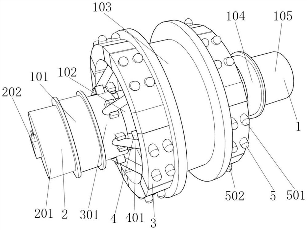
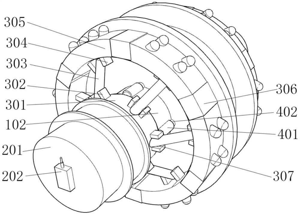
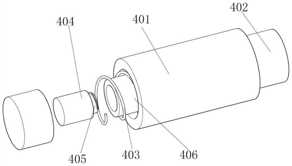
[0028] The present invention provides a bridge crane wheel set structure, including a wheel set structure 1, an induction mechanism 2, a stretching mechanism 3, a power supply mechanism 4, and a friction mechanism 5, and also includes:

[0029] The sensing mechanism 2 is arranged on the outer wall of one end of the wheel structure 1, and the sensing mechanism 2 is fixedly connected to the wheel structu...


PUM


Abstract

The invention relates to the technical field of bridge crane wheel set structures, and discloses a bridge crane wheel set structure, a stretching mechanism further comprises a sliding ring column, the outer wall of the sliding ring column is fixedly connected with a first fixing plate, and the inner wall of the first fixing plate is movably connected with a rotating rod; the outer wall of the rotating rod is fixedly connected with a pulling rod, the other end of the pulling rod is fixedly connected with the rotating rod, the two ends of the rotating rod are fixedly connected with second fixing plates, one ends of the second fixing plates are fixedly connected with fixing semicircular plates, one ends of the fixing semicircular plates are fixedly connected with stretching bodies, and the stretching bodies have certain flexibility. According to the friction mechanism, fixing of the first fixing plate is facilitated by arranging the sliding annular column, force transmission is facilitated by arranging the first fixing plate, the rotating rod, the pulling rod and the second fixing plate, and fixing of the whole friction mechanism is facilitated by arranging the fixing semicircular plate and the stretching body.

Description

technical field [0001] The invention relates to the technical field of wheel set structures of bridge cranes, and more specifically, the invention relates to a wheel set structure of bridge cranes. Background technique [0002] Bridge crane is an important tool and equipment to realize the mechanization and automation of the production process in modern industrial production and lifting transportation, which can reduce the labor intensity of the operator and improve productivity. Logistics turnover and other departments and places have been widely used, it is an indispensable equipment in people's production activities; [0003] During the operation of the bridge crane, the wheel set of the bridge crane is also called the wheel set of the bridge crane, which is used to support the movement of the lifting device. The wheel set of the bridge crane is mainly used on the double girder crane. The operation is of certain importance; [0004] However, when the traditional bridge ...

Claims


Application Information

Patent Timeline
IPC IPC(8): B66C9/08B66C13/16
CPCB66C9/08B66C13/16
Inventor 韩民胜徐鹏飞
Owner HENAN FADA CRANE CO LTD
Why Eureka
Try Eureka