Energy-saving component
A technology of components and driving parts, applied in electrical components, electric components, control of mechanical energy, etc., can solve problems such as motor environmental limitations, difficulty in effectively improving efficiency, frictional force or power conversion loss, etc.
- Summary
- Abstract
- Description
- Claims
- Application Information
AI Technical Summary
Problems solved by technology
Method used
Image

Examples
Embodiment 1
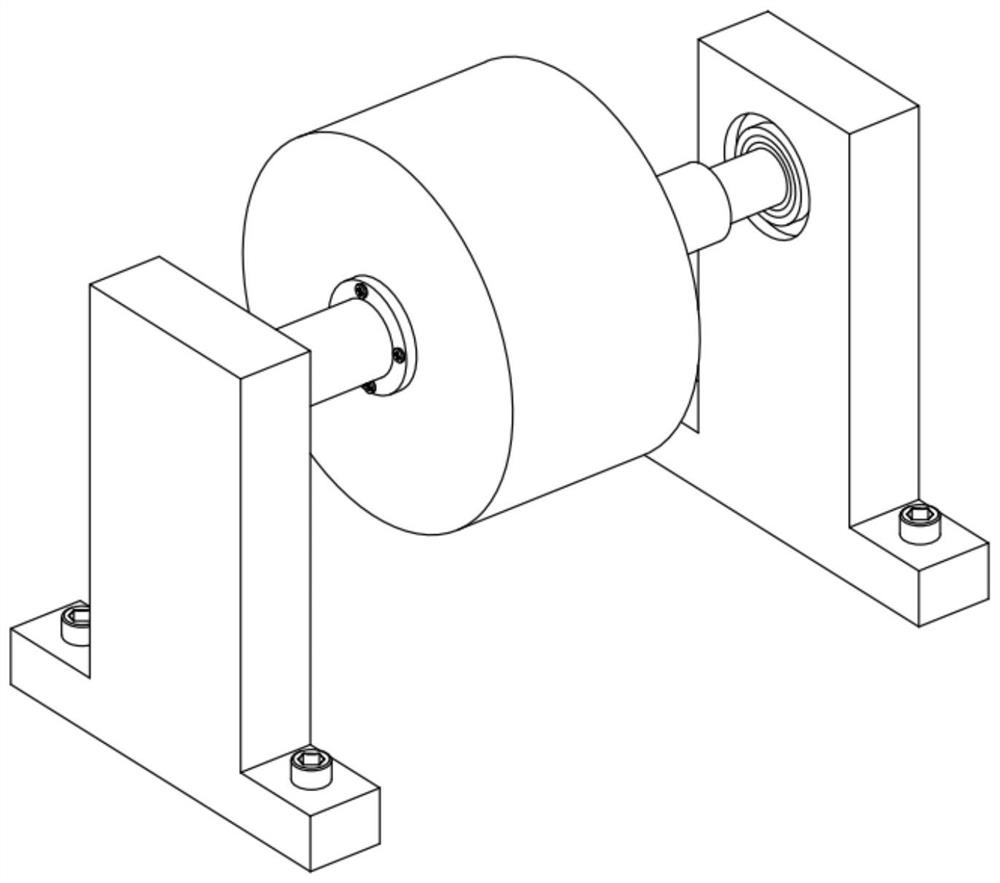
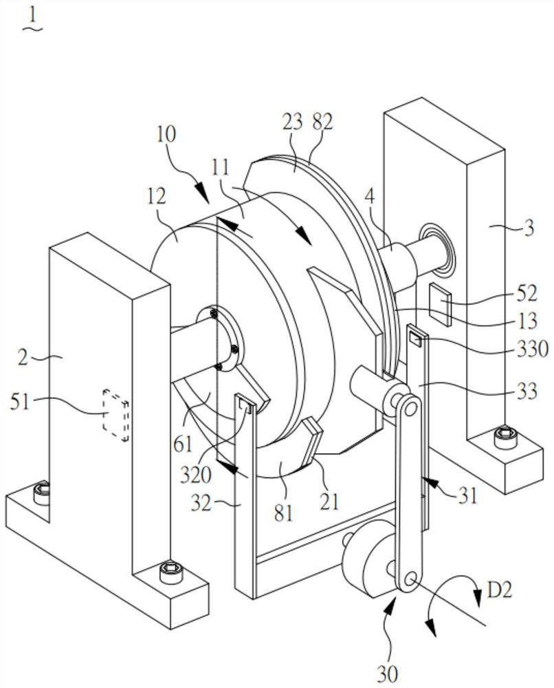
[0109] figure 2 A perspective view showing the energy-saving component of Embodiment 1 of the present creation.
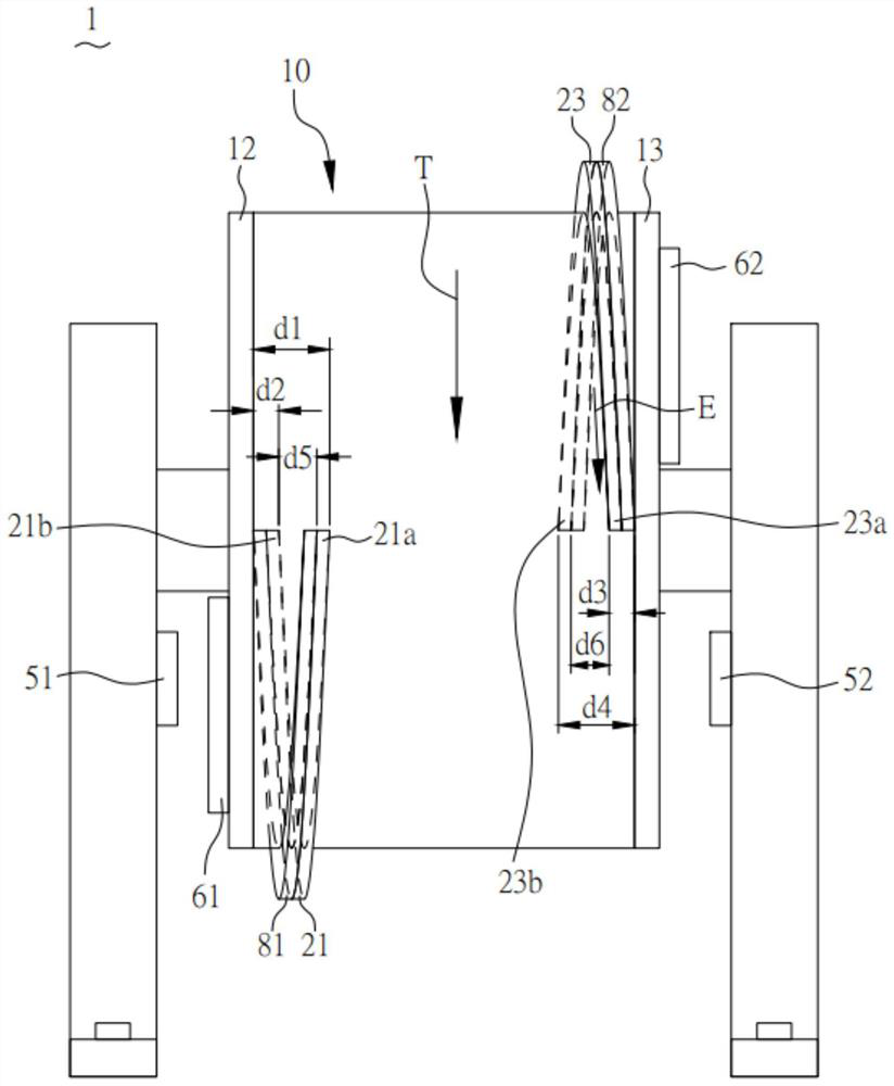
[0110] image 3 A front view of the energy-saving component of Embodiment 1 of the present creation is shown.
[0111] Such as figure 2As shown, in the energy-saving component used for power source in this embodiment, the energy-saving component 1 includes a first side plate 2, a second side plate 3, a shaft center 4, an energy-saving runner 10, a first permanent magnet piece 21, a second Two permanent magnet sheets 23, a magnetic driver 30. Wherein the energy-saving runner 10 is pivotally connected to the first side plate 2 and the second side plate 3 through the shaft center 4, and has an outer surface 11, and the shaft center 4 is connected to an external rotating shaft (not shown in the figure), and through the external The rotating shaft drives the energy-saving runner 10 to rotate, so the energy-saving runner 10 can rotate relative to the first side pla...
Embodiment 2
[0124] Image 6 A perspective view showing the energy-saving component of Embodiment 2 of the present creation.
[0125] Figure 7 A front view of the energy-saving component of Embodiment 2 of the present creation is shown.
[0126] The structure of this embodiment is similar to that of Embodiment 1, and has similar features and functions as Embodiment 1, so it will not be repeated here, and the differences with Embodiment 1 are as follows:
[0127] Such as Image 6As shown, in the present embodiment, the first permanent magnet sheet 21 and the second permanent magnet sheet 23 are similar ring-shaped structures corresponding to the size of the energy-saving runner 10, that is, the first permanent magnet sheet 21 and the second permanent magnet sheet 23 The angle around the energy-saving runner 10 is 360 degrees or approximately 360 degrees, and because the first permanent magnet sheet 21 and the second permanent magnet sheet 23 are 360 degrees or approximately 360 degree...
Embodiment 3
[0132] Figure 9 A perspective view showing the energy-saving component of Embodiment 3 of the present creation.
[0133] Figure 10 A side view of the energy-saving component of Embodiment 3 of the present creation is shown.
[0134] The structure of this embodiment is similar to that of Embodiment 2, and has similar features and functions as Embodiment 2, so it will not be repeated here, and the differences with Embodiment 2 are as follows:
[0135] Such as Figure 9 and Figure 10 As shown, in this embodiment, the energy-saving component 1 has a plurality (such as six, but it can also be increased or decreased) of magnetic driving parts 30, and these magnetic driving parts 30 are electromagnets, and these magnetic driving parts 30 It is fixed on the first side plate 2 and the second side plate 3 and surrounds the energy-saving runner 10, wherein there is a distance between each magnetic drive part 30, so the magnetic drive part 30 can be powered by an external generator...
PUM
 Abstract
Description
Claims
Application Information
 - R&D Engineer
- R&D Manager
- IP Professional
- Industry Leading Data Capabilities
- Powerful AI technology
- Patent DNA Extraction
Browse by: Latest US Patents, China's latest patents, Technical Efficacy Thesaurus, Application Domain, Technology Topic.
© 2024 PatSnap. All rights reserved.Legal|Privacy policy|Modern Slavery Act Transparency Statement|Sitemap