Coaxial transmission device

A coaxial transmission, crankshaft technology, applied in transmissions, belts/chains/gears, mechanical equipment, etc., can solve problems such as limitations

Pending Publication Date: 2022-03-01
크라켄 이노베이션스 게엠베하
View PDF8 Cites 0 Cited by
  • Summary
  • Abstract
  • Description
  • Claims
  • Application Information

AI Technical Summary

Problems solved by technology

[0004] The disadvantage caused by the line contact is that the line contact limits the transferable torque

Method used


Image

  • Coaxial transmission device
  • Coaxial transmission device
  • Coaxial transmission device

Examples


Embodiment Construction

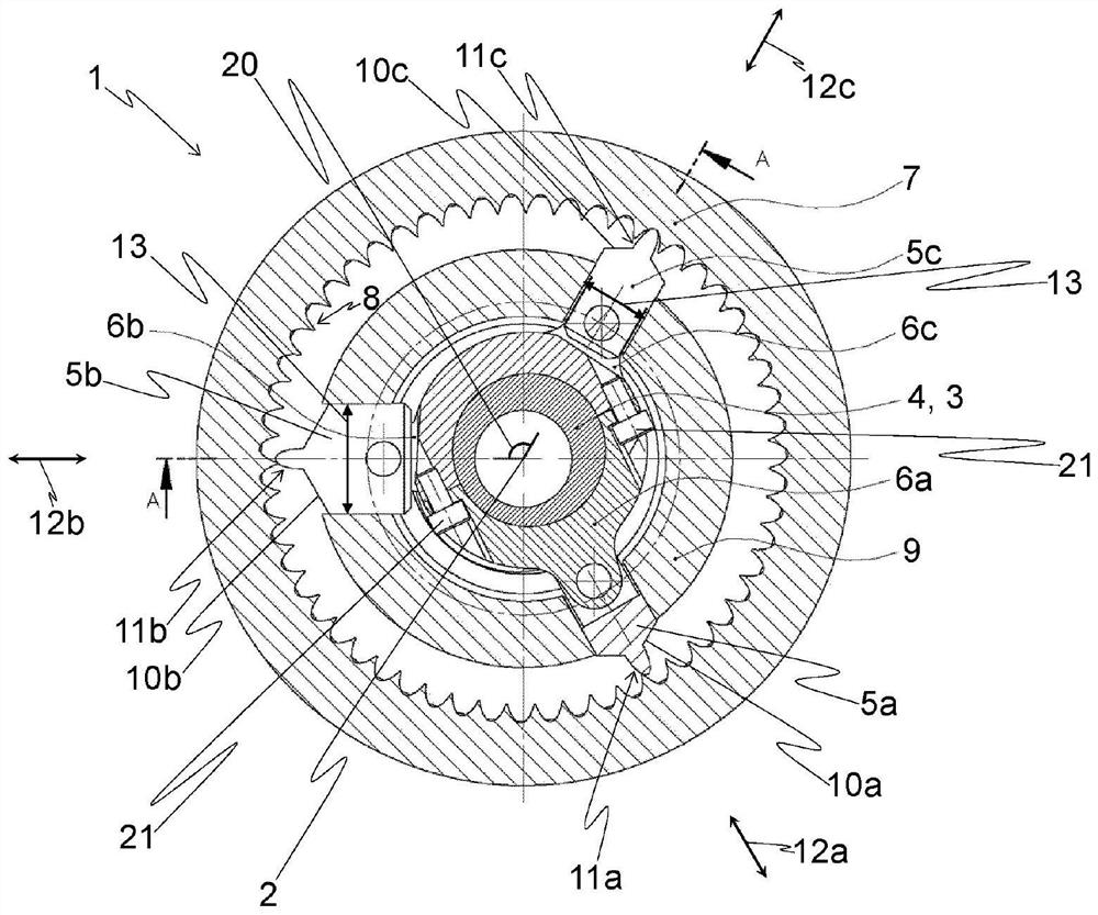
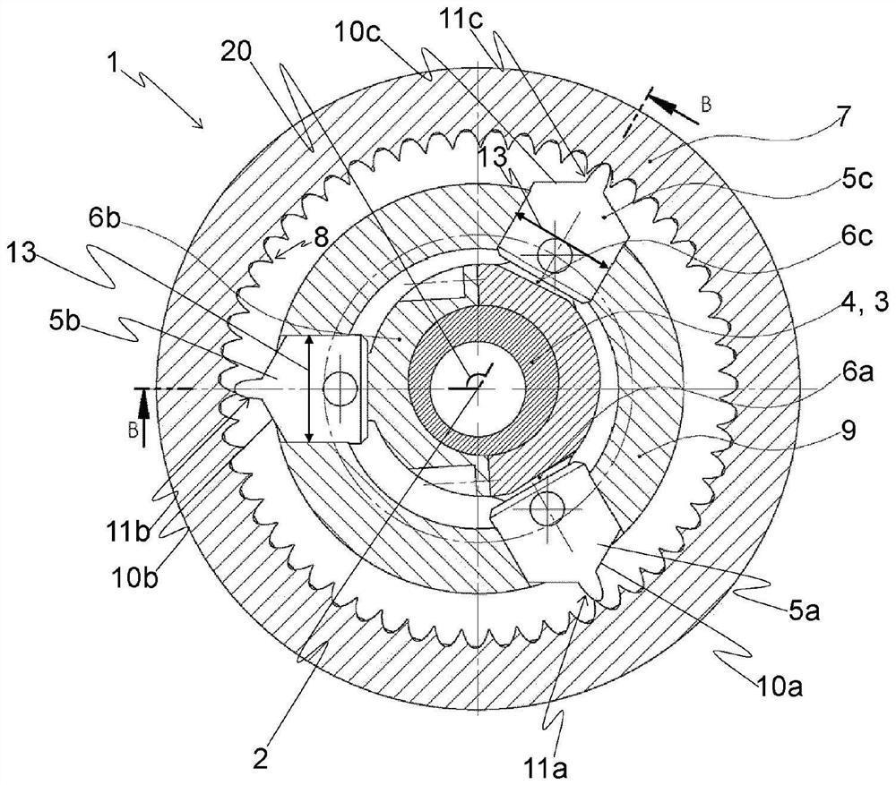
[0063] figure 1 The coaxial transmission 1 or crankshaft transmission according to the invention is shown schematically in a section perpendicular to the axis of rotation 2 . The coaxial transmission 1 comprises a crankshaft 3 rotatable about an axis of rotation 2 with at least one connecting rod bearing 4 , wherein in the exemplary embodiment shown there is exactly one connecting rod bearing 4 or exactly one connecting rod journal or crank pin.

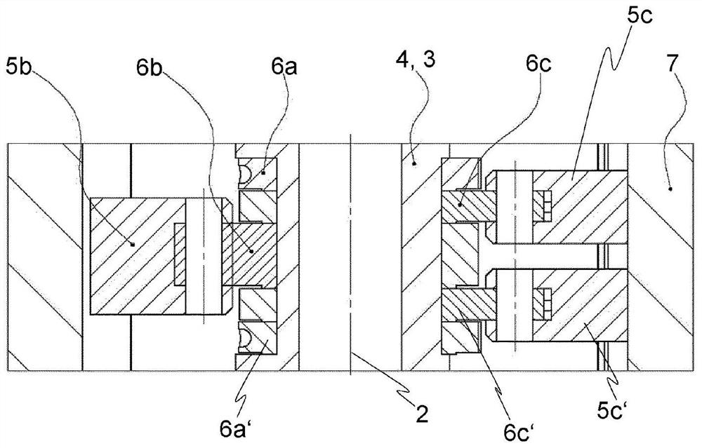
[0064] A plurality of pistons is connected to the connecting rod bearing 4 in a known manner, or the pistons are movably mounted on the connecting rod bearing 4, for example, the separate connecting rod bores of the connecting rods 6a, 6b, 6c are each connected by means of screws 21 (see figure 1 ) is fastened on the connecting rod bearing part 4, and the pistons 5a, 5b, 5c are connected with the other connecting rod holes of the connecting rods 6a, 6b, 6c by means of piston pins. exist figure 1 In the embodiment, a total of five...


PUM


Abstract

The invention relates to a coaxial transmission (1), comprising: a crankshaft (3) which can be rotated about an axis of rotation (2) and has at least one connecting rod bearing (4); a plurality of, preferably at least three, pistons (5a, 5b, 5c), which are each connected to the at least one connecting rod bearing by means of a connecting rod (6a, 6b, 6c) and which each have a toothing (11a, 11b, 11c) on a first end face (10a, 10b, 10c) facing away from the axis of rotation, said toothing having at least one tooth; the invention relates to a coaxial transmission (1) comprising a hollow shaft (7) having an internal toothing (8), said pistons being arranged inside the hollow shaft as viewed in a plane perpendicular to the axis of rotation, and a guide unit (9), said pistons being linearly guided in each case in the guide unit, said pistons being reciprocally movable parallel to a radial direction (12a, 12b, 12c) which is perpendicular to the axis of rotation, as a result, the teeth on the first end side of the piston can be brought into engagement with the internal teeth and into disengagement from the internal teeth in succession.

Description

technical field [0001] The invention relates to a coaxial transmission comprising a crankshaft rotatable about an axis of rotation and having at least one connecting rod bearing. Background technique [0002] A self-locking transmission is known from DE 312 164 C, wherein a plurality of arms arranged in a star shape around the drive shaft are supported eccentrically on the drive shaft with their inner ends, with their intermediate parts in guides, and Engage with the gear ring with its outer end. Here, the arms are designed as double-armed levers, the pivot point of which is guided in the manner of a crosshead, and the inner ends of the levers are mounted independently of each other on the driving eccentric, so that the outer ends implement The connecting rod moves and here in turn engages the ring gear and drives it in the opposite direction to the rotation of the drive shaft. This results in a cycloidal motion and thus brings the outer end into linear contact with the te...

Claims


Application Information

Patent Timeline
Patent Type & Authority Applications(China)
IPC IPC(8): F16H49/00F16H25/06
CPCF16H25/06F16H49/001F16H25/2003F16H2025/2037
Inventor P·S·艾瑟勒M·米切利奇
Owner 크라켄 이노베이션스 게엠베하
Why Eureka
Try Eureka