Circular comb for circular comber

A technology of combing machine and circular comb, applied in the field of circular combing of combing machine, can solve the problems of undesired vibration of the device, shorten the service life, etc., and achieve the effect of increasing the value of the comb jaws

Inactive Publication Date: 2007-07-18
MASCHINENFABRIK RIETER AG
View PDF6 Cites 0 Cited by
  • Summary
  • Abstract
  • Description
  • Claims
  • Application Information

AI Technical Summary

Problems solved by technology

Also, in good cases, this can lead to undesired vibrations of the unit, which in turn reduces the service life

Method used


Image

  • Circular comb for circular comber
  • Circular comb for circular comber
  • Circular comb for circular comber

Examples


Embodiment Construction

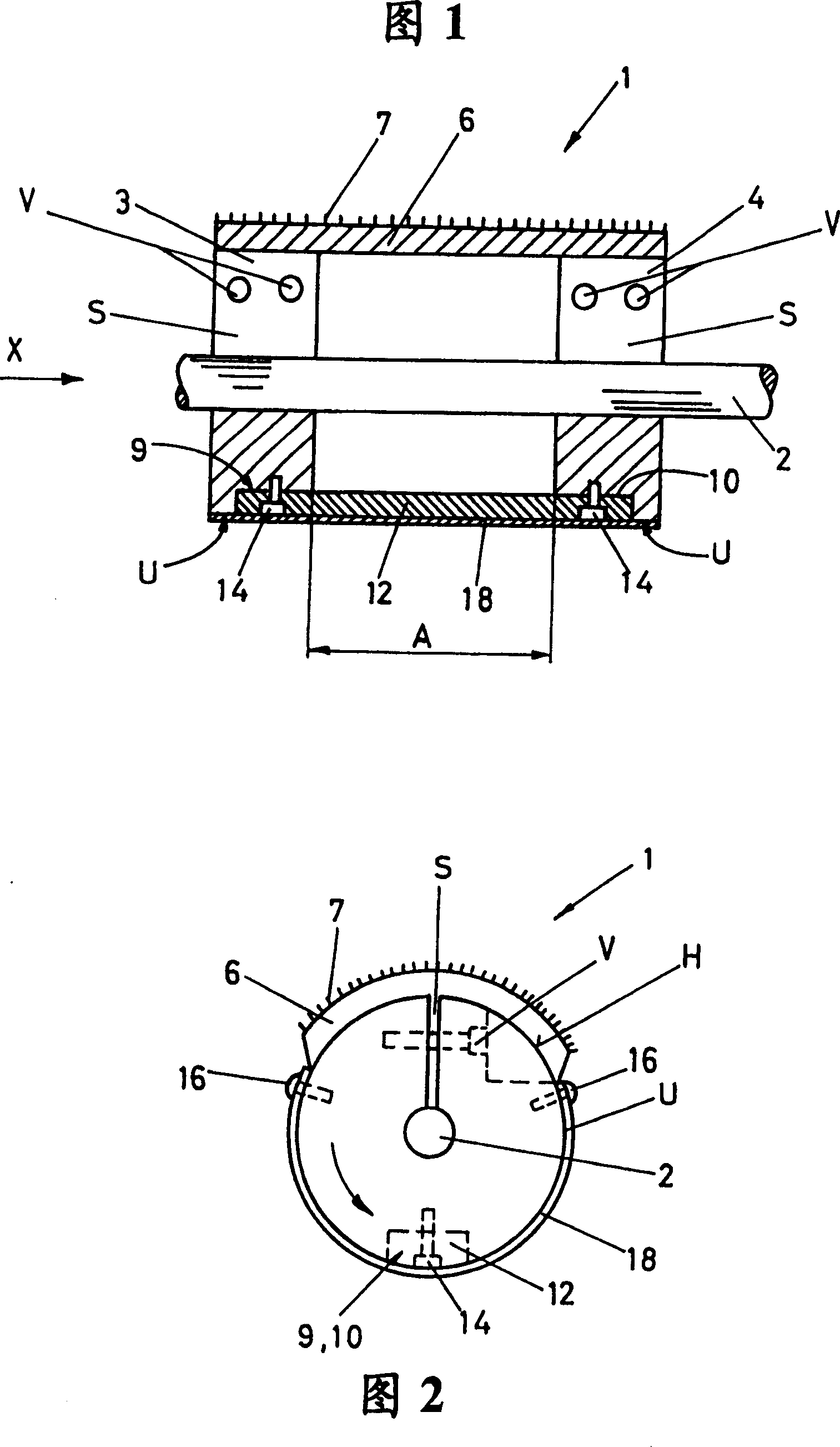
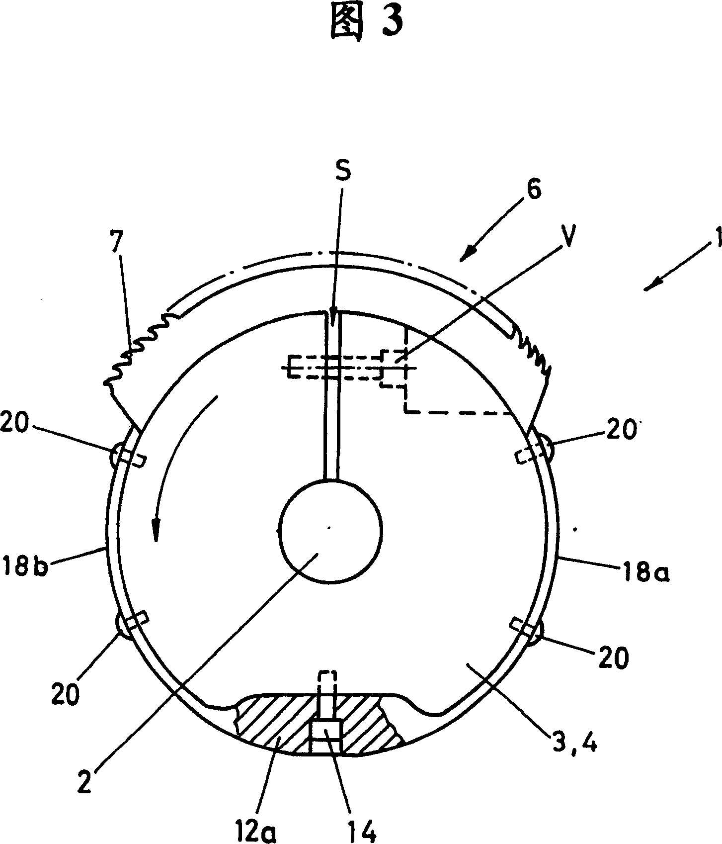
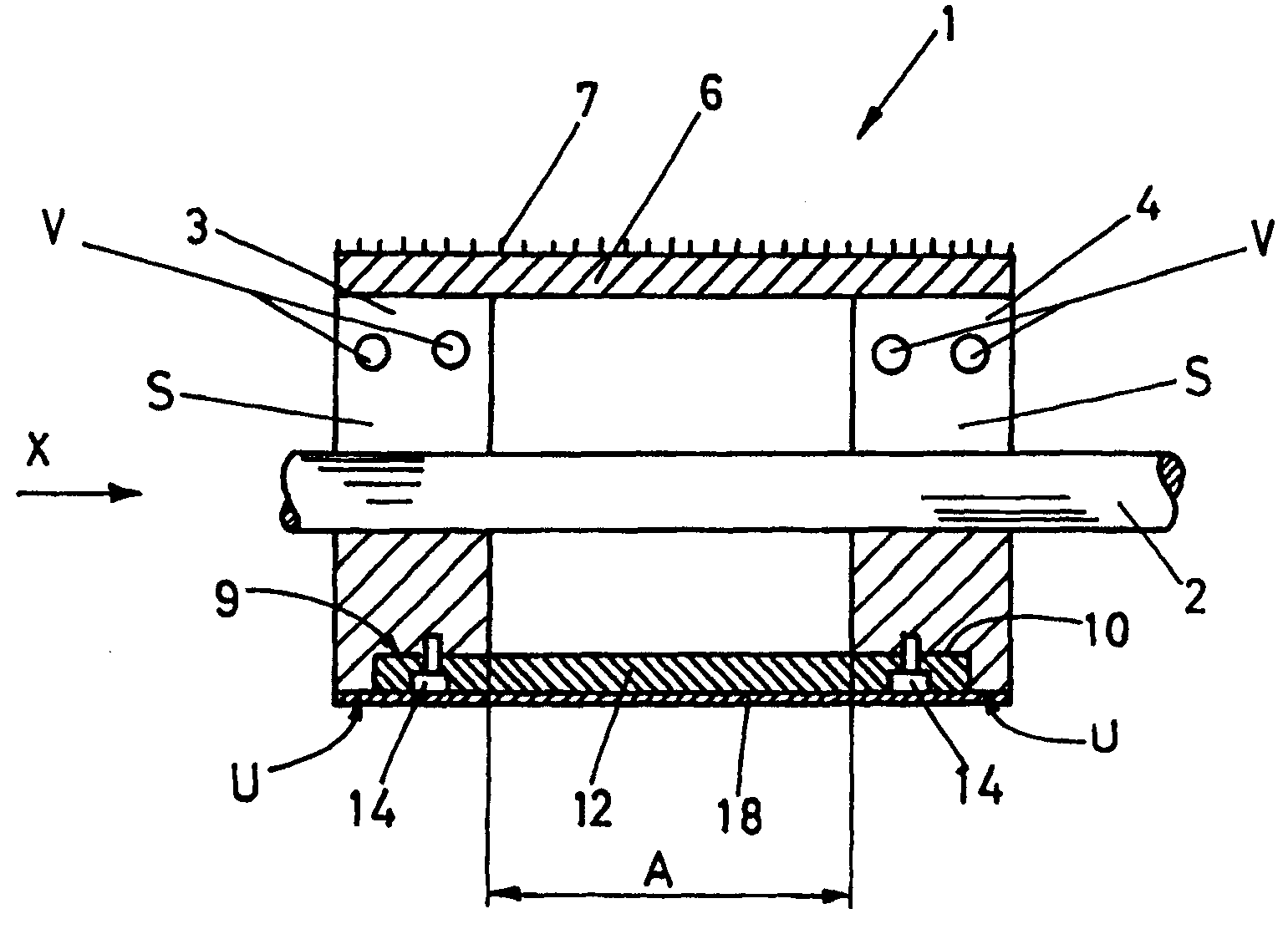
[0027] The circular comb 1 shown in FIG. 1 has a circular comb shaft 2 to which the disk parts 3 , 4 are fastened in a rotationally fixed manner. The disc members 3, 4 are in each case provided with a slot S, which can be firmly clamped on the shaft 2 by means of a threaded connection V, as shown schematically in the figure. The circular comb part 6 is fixed to the disc members 3, 4 by a not shown screw connection, the circular comb is provided with a comb structure 7, shown schematically in the figure, for combing a mass of fibers by means of not shown jaws.

[0028] The counterweight 12 is fixed to the cutouts 9 , 10 on the disc members 3 , 4 of the opposing circular comb portion 6 by means of schematically shown screws 14 . A cover 18 in the form of a sheet metal casting is fastened by screws 16 to the circumference of the disc members 3, 4 so as to cover the free space between the disc members 3, 4. The purpose of this is to suppress the uncontrolled flow of air, which co...


PUM


Abstract

The invention relates to a circular comb (1) for circular comber with circular comb supports (3, 4) fixed on a shaft (2) by antirotation means, at least one circular comb part (6) fixed on a part circumference surface (U) of support, thereby a counterweight (12) of the circular comb part (6) is set on radial direction opposite to broadside thereof. In order to non-continously drive the circular comb and operate with higher circular comb tong door value, and avoid unwished vibration, the circular comb support is composed by at least one disk part (3, 4) for holding circular comb part (6) and one or several counterweight (12, 12a), thereby disk part (3, 4) connect with counterweight (12, 12a), specific gravity of disk part (3, 4) is less than that of counterweight (12, 12a).

Description

technical field [0001] The invention relates to a circular comb of a combing machine with a circular comb carrier fixed to the shaft in a torsion-resistant manner, at least one circular comb part fixed on a part of the circumference of the carrier for the circular comb part The counterweights of the mass compensator are arranged on diametrically opposite sides of the circular comb portion. Background technique [0002] This circular comb is used for combing machines to process fibers (cotton, wool, etc.). As a result, the processed fibers are in the form of a roll wound on a bobbin (simply called a roll) or in the form of a fiber tape. [0003] The number of nips in circular combs (the number of circular comb nips per minute) has increased considerably over the past few years, which equates to an increase in production. [0004] Demand has increased for circular combs of this type that are no longer operated at continuous rotational speed, but are driven in intermittent ci...

Claims


Application Information

Patent Timeline
IPC IPC(8): D01G19/10
CPCD01G19/10
Inventor B·怀曼M·托布勒
Owner MASCHINENFABRIK RIETER AG
Why Eureka
Try Eureka