Double comb cage with mass balance for double row cylindrical roller bearings

A cylindrical roller bearing, double-comb technology, applied in the direction of roller bearings, bearing components, shafts and bearings, to achieve the effect of mass distribution avoidance

Inactive Publication Date: 2015-12-16
SCHAEFFLER TECH AG & CO KG
View PDF6 Cites 0 Cited by
  • Summary
  • Abstract
  • Description
  • Claims
  • Application Information

AI Technical Summary

Problems solved by technology

However, due to the slope of the webs of a support row and the mounting grooves on the side of the cage, an asymmetrical mass distribution with the above-mentioned disadvantageous effects results

Method used


Image

  • Double comb cage with mass balance for double row cylindrical roller bearings
  • Double comb cage with mass balance for double row cylindrical roller bearings
  • Double comb cage with mass balance for double row cylindrical roller bearings

Examples


Embodiment Construction

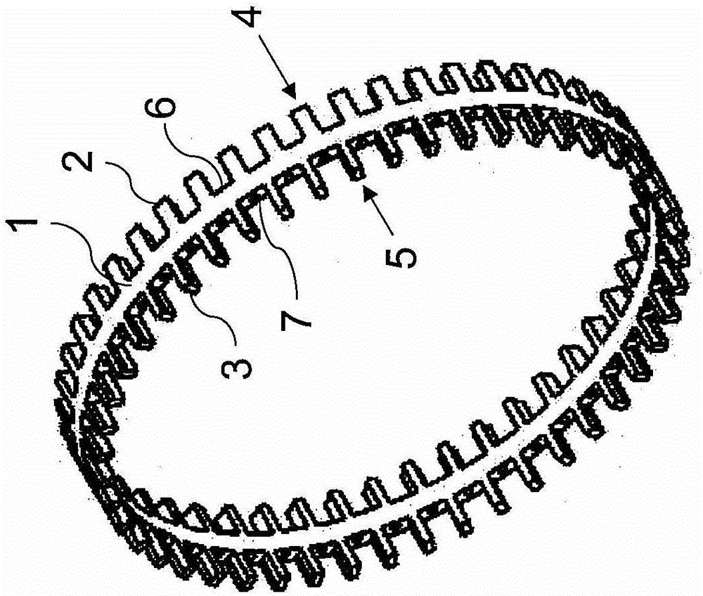
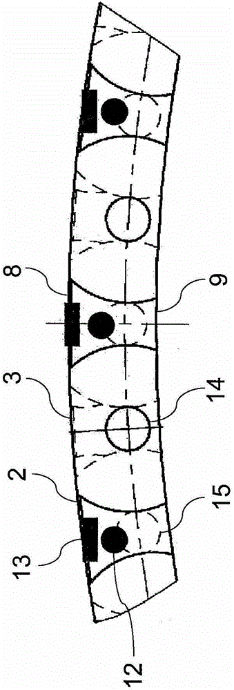
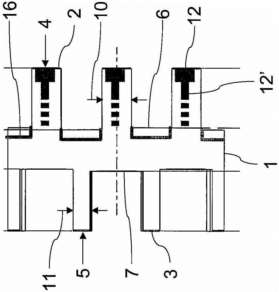
[0026] figure 1The double-comb cage for double-row cylindrical roller bearings, for example made of brass in one piece and combined into a ring, shown in , comprises a central ring 1 extending axially from both sides of the ring The webs 2, 3 are offset from each other. The webs 2 , 3 on both axial sides of the cage are arranged evenly distributed over the circumference and accordingly form bearing rows 4 , 5 for rolling elements or cylindrical rollers (not shown). Each two adjacent webs 2 or 3 form a receiving pocket 6 or 7 for a cylindrical roller. In order to clamp and support the cylindrical rollers in the receiving pockets 6, 7, such as figure 2 As shown in , the webs 2 , 3 can be contoured in a manner known per se between the radially outer bottom side 8 and the radially inner bottom side 9 . The not shown outer and inner rings of the cylindrical roller bearing are likewise designed in a manner known per se and will not be described in detail here.

[0027] The webs...


PUM


Abstract

The invention relates to a double-comb cage for double-row cylindrical roller bearings, which has a central ring (1) from which webs (2, 3) protrude axially on both sides, wherein The webs ( 2 ; 3 ) on one side together with the rolling elements arranged there correspondingly form a bearing row ( 4 ; 5 ), wherein every two adjacent webs ( 2; 3) Delimit the receiving pockets (6; 7) for the rolling bodies, and wherein the webs (3) are narrowed in the circumferential direction at least in one bearing row (5) for The receiving pockets (7) are radially filled with the rolling elements. In order for the double-comb cage to have satisfactory running properties and to be produced relatively simply and cost-effectively, on the other of the two bearing rows (4; 5) there is a device for connecting the two bearing rows ( 4; 5) forming recesses ( 12 , 12 ′, 13 , 14 , 16 ) for symmetrical mass distribution.

Description

technical field [0001] The invention relates to a double-comb cage for double-row cylindrical roller bearings, which has a central ring from which webs protrude axially on both sides, wherein the webs on one side are aligned with the The rolling bodies there together accordingly form a bearing row, wherein each two adjacent webs of a bearing row delimit a receiving pocket for the rolling bodies, and wherein at least in one bearing row the webs extend in the circumferential direction The narrowing is designed to radially fill the receiving pockets with the rolling elements. Background technique [0002] Multi-row cylindrical roller bearings are already known. They are used, for example, in larger vehicle transmissions, in the transmission of mechanical equipment or in machine tools, for example as support rollers in rolling equipment, in which the rolling bearings are subjected to high radial and optionally also axial loads and / or high rotational speeds . In such a bearing...

Claims


Application Information

Patent Timeline
Patent Type & Authority Patents(China)
IPC IPC(8): F16C33/48F16C33/49F16C33/46F16C43/06F16C19/28
CPCF16C19/28F16C33/467F16C33/48F16C33/49F16C33/494F16C43/06F16C43/065F16C33/46
Inventor 卡尔·穆勒维尔纳·罗曼
Owner SCHAEFFLER TECH AG & CO KG
Why Eureka
Try Eureka