

Piston-cylinder unit
A technology of piston cylinder and equipment, applied in mechanical equipment, door/window fittings, shock absorbers, etc., can solve problems such as damage, personal injury, loose casing and pressure pipe, etc.
- Summary
- Abstract
- Description
- Claims
- Application Information
AI Technical Summary
Problems solved by technology
Method used
Image

Examples
Embodiment Construction
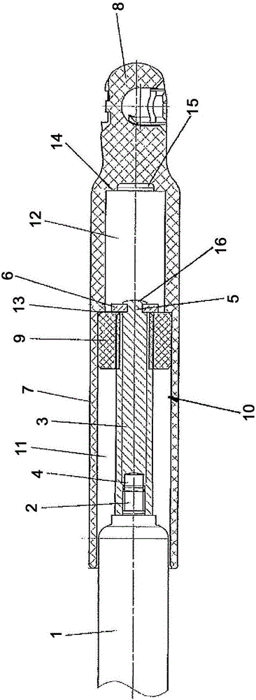
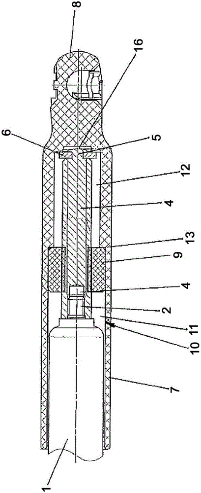
[0025] The illustrated piston-cylinder arrangement is designed to lift, for opening, a tailgate of the vehicle, which is pivotable about a horizontal axis, from a largely downwardly directed closed position into an open position. The piston-cylinder arrangement has a pressure tube 1 of an air spring, at a first end (not shown) of which a piston rod is guided sealingly outward, which carries a first connecting piece at its free end. The first connection part can be a universal joint, which can be fastened to the trunk lid or the body of the vehicle.
[0026] The shown second end of the pressure tube 1 is closed and has an axially protruding threaded journal 2 . The threaded spindle 3 is screwed onto the threaded journal 2 with a threaded bore 4 formed coaxially at one end thereof.
[0027] A nut 9 , for example made of plastic, is screwed onto the threaded spindle 3 .
[0028] The end of the lead screw 3 opposite the threaded hole 4 is designed as a rivet pin 5, the stop wash...
PUM
 Abstract
Description
Claims
Application Information